Proximity sensors are indispensable components in modern industrial automation, providing non-contact detection of metallic or non-metallic objects. Correct wiring is fundamental to ensuring reliable operation, safety, and longevity of these sensors within a control system. This tutorial outlines standard wiring methods for both 2-wire and 3-wire DC proximity sensors, which are the most common types encountered in the field.
Before beginning any wiring procedure, always consult the specific sensor's datasheet for its electrical characteristics, such as operating voltage, current consumption, and output type (PNP or NPN, normally open or normally closed). Ensure the power supply is disconnected and locked out/tagged out (LOTO) to prevent accidental energization.
Wiring a 2-Wire DC Proximity Sensor
The 2-wire sensor is the simplest to connect, as it operates similarly to a mechanical switch. It has only two terminals: one for power (typically labeled +V or L+) and one for load (labeled L- or simply the output). These sensors can be connected in series with the load, regardless of polarity for AC versions, but DC versions require correct polarity.
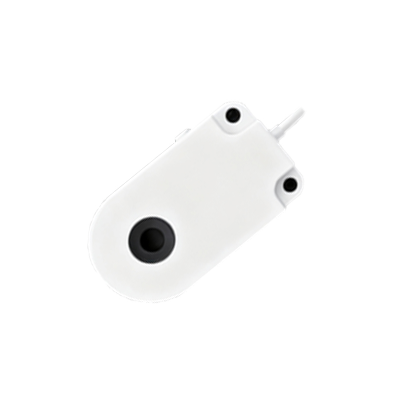
1. Connect one wire from the positive terminal of your DC power supply (e.g., 24VDC) to the positive terminal (+V) of the sensor.
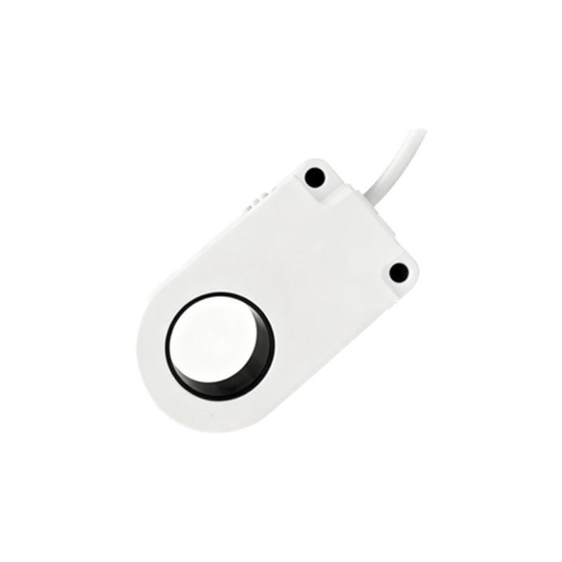
2. Connect the load terminal (L-) of the sensor to one terminal of your load device (e.g., a PLC input module, relay coil, or indicator lamp).
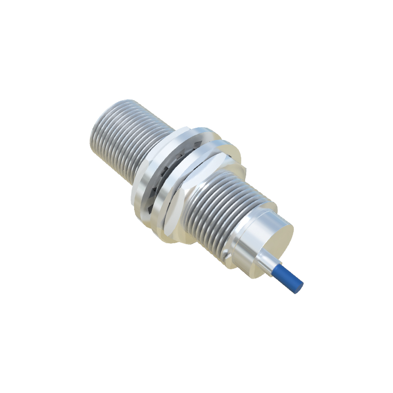
3. Connect the other terminal of the load device back to the negative terminal of the DC power supply.
This forms a complete series circuit. When the sensor detects a target, it closes its internal switch, allowing current to flow from the supply, through the sensor, through the load, and back to the supply, thereby activating the load. A key consideration is the sensor's leakage current in the "off" state, which must be lower than the holding current of the load to prevent unintended activation.
Wiring a 3-Wire DC Proximity Sensor
Three-wire sensors offer superior performance with separate power and output wires, minimizing leakage current issues. They come in two primary output configurations: PNP (sourcing) and NPN (sinking). The wiring color code is typically brown for +V (power), blue for 0V (common), and black for the output signal.
For a PNP (Sourcing) Sensor:
1. Connect the brown wire to the positive terminal of your DC power supply (e.g., +24VDC).
2. Connect the blue wire to the negative terminal (0V) of the same power supply.
3. Connect the black (output) wire to your load device (e.g., a PLC digital input).
4. Connect the other terminal of the load device to the power supply's 0V (negative) terminal.
In this configuration, when activated, the PNP sensor sources current from its output (black wire) to the load. The load's other side is connected to 0V to complete the circuit.
For an NPN (Sinking) Sensor:
1. Connect the brown wire to the positive terminal of your DC power supply (e.g., +24VDC).
2. Connect the blue wire to the negative terminal (0V) of the same power supply.
3. Connect one terminal of your load device to the positive terminal of the power supply.
4. Connect the other terminal of the load device to the black (output) wire of the sensor.
Here, when activated, the NPN sensor sinks current from the load into its output. The load is powered from +V, and the sensor provides a path to 0V when triggered.
Critical Best Practices and Troubleshooting
- Shielded Cable: Always use shielded cable in electrically noisy environments. Connect the cable shield to a proper earth ground at the control panel end only, leaving the sensor end unconnected and insulated to prevent ground loops.
- Short-Circuit Protection: Ensure the power supply or the connected controller (like a PLC) has built-in protection against output short circuits, which is common for many modern sensors.
- Load Compatibility: Verify that the sensor's maximum switching current and voltage ratings are not exceeded by the connected load.
- Wiring Integrity: Use ferrules on stranded wires for screw terminals to prevent stray strands and ensure a secure, gas-tight connection. Route sensor cables away from high-voltage power lines and motor drives to mitigate electromagnetic interference (EMI).
- Diagnostic LEDs: Most sensors have an LED indicator