In industrial automation and process control systems, hourglass proximity sensors are critical components for non-contact detection, often used in packaging, material handling, and assembly lines. A common and frustrating issue encountered by maintenance engineers and technicians is the sensor's display failing to show any data or status indicators. This failure can lead to unexpected downtime, production halts, and potential safety concerns. This guide provides a systematic, engineer-level approach to diagnosing and resolving display failures in hourglass-type proximity sensors.
The first step in any troubleshooting process is to understand the system context. An hourglass proximity sensor typically consists of the sensing element (often inductive or capacitive), an integrated signal processing unit, and a local display module, which is usually a simple digital readout or LED indicators. The display's primary function is to show operational status—such as power ON, detection mode, sensing distance, or fault codes—providing immediate visual feedback. A complete display failure, where no segments illuminate, is distinctly different from a display showing erroneous data or a specific error code. Isolate the problem: is it solely a display issue, or is the sensor itself also not functioning? Often, the sensor may still be operating and sending signals to the PLC via its output circuit (PNP/NPN) even if the display is dead. Verifying the sensor's output with a multimeter or PLC input status check is a crucial preliminary step.
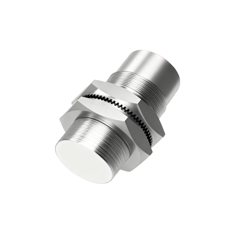
The most probable root cause of a non-illuminating display is a power supply problem. Begin verification at the source. Confirm that the sensor is receiving the correct voltage as per its specifications (commonly 10-30V DC). Use a calibrated multimeter to measure the voltage directly at the sensor's power terminals. Ensure the polarity is correct. Voltage that is too low, too high, or unstable can prevent the display circuitry from initializing. Check for voltage drops along the cable run, especially in long installations. Inspect the wiring for loose connections, corrosion, or damaged insulation that could cause an intermittent or absent power connection. Do not overlook the grounding; a poor ground can cause erratic behavior in the display and the sensor's logic.
If power is confirmed to be stable and within specification, the next focus is on the display module itself and its connection to the main sensor board. Many hourglass sensors have a separate, ribbon-cable-connected display unit. Over time, vibration and thermal cycling can cause these internal connectors to become loose. In some models, the display is a sealed unit, but internal solder joints on the display driver IC or related components can fail. Environmental factors are significant contributors. Contamination by dust, metallic shavings, moisture, or chemical exposure can short circuit the delicate traces on the display's PCB. Condensation inside the housing is a frequent culprit in environments with large temperature swings. A thorough visual inspection under magnification can reveal corrosion, burnt components, or cracked solder joints.
Another critical area is the sensor's configuration or mode setting. Some proximity sensors have a programming mode or a "display off" feature to conserve power or reduce light in sensitive environments. Accidentally entering this mode via the teach-in button or external programming tool can make it appear as if the display has failed. Consult the manufacturer's manual to perform a hard reset or recalibration procedure. This often involves a specific sequence of power cycling and button presses, which can restore default parameters and potentially revive the display.
In cases where power, connections, environment, and configuration are ruled out, the fault likely lies within the internal electronics. The voltage regulator supplying the display logic may have failed. The microcontroller unit (MCU) responsible for driving the display might be corrupted or damaged due to an electrical transient, such as an induced voltage spike from nearby motors or solenoids. While field repair of surface-mount electronics is often impractical, identifying this cause helps in deciding the corrective action: board replacement or entire sensor replacement.
Proactive measures are essential to prevent recurrence. Ensure sensors are selected with an appropriate IP (Ingress Protection) rating for the environment. Implement proper electrical protection, such as surge suppressors and stable, filtered power supplies. Follow correct installation guidelines, including secure cable strain relief to prevent wire breakage at the terminals. Establish a routine preventive maintenance schedule that includes cleaning sensor faces and checking electrical connections.
When the display failure is accompanied by a complete loss of sensing function, the problem is more fundamental, likely involving the oscillator circuit or the output driver stage. In such scenarios, sensor replacement is usually the most cost-effective solution given the criticality of the application. Always keep a record of the failure symptoms, measurements taken, and the final resolution. This data is invaluable for identifying recurring issues and improving system reliability.