In industrial automation and control systems, proximity sensors play a critical role in detecting the presence or absence of objects without physical contact. Among various types, the two-wire proximity sensor is widely favored for its simplicity and ease of integration into existing circuits. This article delves into the wiring diagram and operational principles of a two-wire proximity sensor, providing insights for engineers and technicians in the electrical and automation fields.
A two-wire proximity sensor, as the name implies, requires only two wires for connection: one for power supply and the other for the load. This design contrasts with three-wire or four-wire sensors, which have separate wires for power, ground, and output signals. The two-wire sensor integrates these functions, making it a cost-effective and space-saving solution. Typically, it operates on DC or AC voltage, commonly ranging from 10 to 30 VDC or 20 to 250 VAC, depending on the model and application requirements.
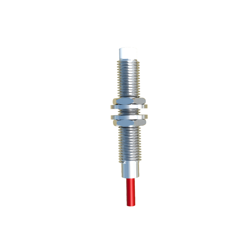
The wiring diagram of a two-wire proximity sensor is straightforward. It consists of two terminals: one connected to the positive side of the power supply (for DC sensors) or the live wire (for AC sensors), and the other connected to the load, such as a relay, programmable logic controller (PLC) input, or an indicator lamp. The load is then connected back to the negative side of the power supply or the neutral wire, completing the circuit. When no target object is within the sensor's detection range, the sensor presents a high impedance state, allowing only a small leakage current to flow—typically a few milliamperes. This leakage current is insufficient to activate the load, keeping it in an "off" state.
Upon detecting a target object, the sensor switches to a low impedance state, allowing sufficient current to flow through the circuit to energize the load. The switching mechanism relies on an internal oscillator and amplifier circuit. In inductive proximity sensors, which detect metallic objects, a coil generates an electromagnetic field. When a metal object enters this field, it induces eddy currents, dampening the oscillator's amplitude. This change is detected by the amplifier, triggering the output switch. For capacitive sensors, used for non-metallic materials, the principle involves changes in capacitance when an object alters the dielectric constant near the sensing face.
Key considerations in wiring include voltage drop and residual current. Since the sensor and load share the same circuit, the voltage drop across the sensor must be minimal to ensure the load receives adequate voltage. Manufacturers specify maximum voltage drop values, often around 2-3 volts. Residual current, or leakage current, is another factor; it must be low enough to prevent accidental activation of sensitive loads. Engineers should consult datasheets to match sensor specifications with load characteristics.
Installation practices are crucial for optimal performance. The sensor should be mounted securely, with the sensing face oriented correctly toward the target. Environmental factors like temperature, humidity, and electromagnetic interference can affect operation, so selecting sensors with appropriate IP ratings and shielding is essential. Additionally, wiring should follow industry standards, using proper gauges and insulation to prevent short circuits or signal degradation.
In summary, the two-wire proximity sensor offers a streamlined approach to object detection in automated systems. Its wiring diagram reflects simplicity, but understanding the underlying principles—such as impedance switching, leakage current, and voltage requirements—is vital for reliable implementation. By mastering these aspects, engineers can enhance system efficiency and reduce downtime in industrial applications.