In industrial automation and control systems, proximity switches and various sensors form the backbone of efficient machinery operation. Understanding the correct wiring methodologies is crucial for ensuring reliability, safety, and optimal performance. This guide provides a comprehensive overview of standard wiring practices for proximity switches and common industrial sensors, adhering to global electrical standards.
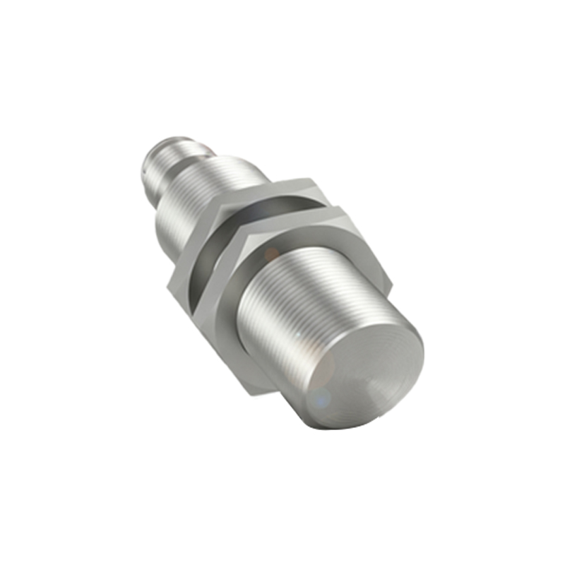
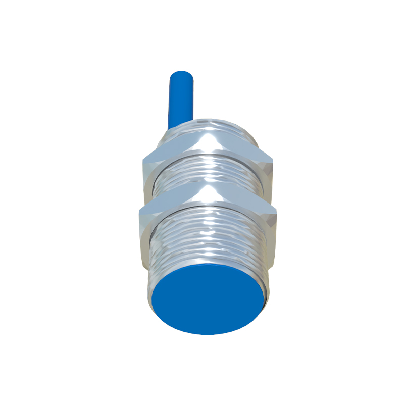
Proximity switches, including inductive, capacitive, and photoelectric types, are non-contact sensors that detect the presence or absence of an object. Their wiring typically involves three or four wires, depending on the output type (PNP or NMP sourcing) and function. A standard three-wire DC proximity switch includes wires for power supply positive (brown), power supply negative (blue), and output signal (black). For a PNP (sourcing) configuration, the load is connected between the output wire and the negative terminal. When the sensor detects a target, it switches the output to supply voltage, completing the circuit to the load. Conversely, an NPN (sinking) configuration connects the load between the positive terminal and the output wire; the output switches to ground upon detection.
Four-wire sensors often incorporate two output channels (e.g., normally open and normally closed) or include diagnostic feedback lines. It is imperative to consult the manufacturer's datasheet for specific pinouts and voltage ratings. Always ensure the power supply voltage matches the sensor's specifications, typically ranging from 10-30V DC for DC sensors and 20-250V AC for AC types. Incorrect voltage application is a leading cause of sensor failure.
Shielding and grounding practices are paramount, especially in environments with electromagnetic interference (EMI). Use shielded cables for signal wires, with the shield grounded at only one end—preferably at the control panel—to prevent ground loops. Maintain proper separation between power cables and signal cables; running them in parallel in the same conduit can induce noise, leading to erratic sensor behavior. For long cable runs exceeding the manufacturer's recommended length (often 100 meters for standard sensors), consider using relay amplifiers or repeaters to boost the signal integrity.
When integrating multiple sensors into a programmable logic controller (PLC) or a relay module, careful planning of the common point is essential. In a system using multiple PNP sensors, the negative terminals are typically tied to a common DC negative bus. Each sensor's output wire is then connected to a separate PLC input. The PLC input card must be configured as sinking to match the PNP sourcing output. For NPN sensors, the common point is the positive bus, and the PLC input card must be sourcing. Mismatching sensor output types and input card configurations will result in non-operation.
For analog sensors (e.g., 4-20mA current loop or 0-10V voltage output), wiring requires attention to detail. A two-wire 4-20mA sensor is loop-powered, meaning the same two wires carry both the power and the signal. The positive wire connects to the positive supply, and the negative wire connects to the PLC's analog input positive, with the input's negative returning to the supply negative, completing the loop. A three-wire analog sensor has separate wires for power positive, power negative, and the signal output. Ensure the analog input module is correctly configured for current or voltage measurement.
Safety is non-negotiable. Always de-energize the circuit before commencing any wiring work. Use appropriate wire gauges as per the current rating; 18-22 AWG is common for sensor circuits. Implement fuses or circuit breakers on power lines to protect against short circuits. For critical safety applications, such as emergency stop circuits or guard door monitoring, use safety-rated sensors (e.g., with dual channels and cross-monitoring) and wire them according to relevant safety standards like ISO 13849.
Troubleshooting common wiring issues often involves a systematic approach. If a sensor fails to trigger, verify power supply presence and polarity at the sensor terminals using a multimeter. Check for loose connections or damaged cables. Ensure the sensing distance and target material are within specifications; inductive sensors, for instance, detect only metals. For erratic operation, investigate potential EMI sources and verify grounding integrity.
In summary, meticulous adherence to wiring diagrams, manufacturer specifications, and industry best practices ensures that proximity switches and sensors deliver long-term, fault-free service. Proper installation not only maximizes equipment uptime but also safeguards personnel and assets, forming a critical component of any robust industrial control system.