Connecting a laser sensor is a fundamental task in industrial automation, requiring precision and adherence to safety protocols. This guide provides a comprehensive, step-by-step approach to ensure reliable integration into your electrical systems.
First, gather all necessary components: the laser sensor unit, a compatible power supply (typically 12-24V DC, but verify the sensor's datasheet), appropriate cables (often shielded cables to reduce electromagnetic interference), and the target controller (e.g., PLC, microcontroller, or data acquisition system). Always power down the entire system before beginning any connections to prevent electrical hazards or damage to sensitive electronics.
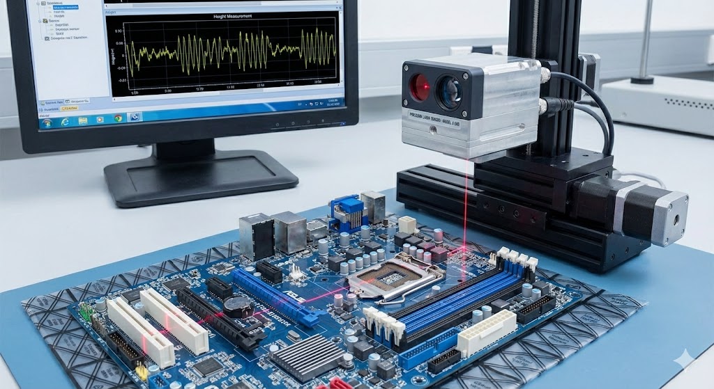
Start by examining the laser sensor's wiring diagram, usually found in its manual or on the housing. Most industrial laser sensors have a standard pin configuration: brown wire for positive voltage (V+), blue wire for negative or ground (V-), black wire for output signal (often NPN or PNP type), and sometimes white or gray wires for additional functions like teach-in or analog output. Confirm whether your sensor is sourcing (PNP) or sinking (NPN), as this determines compatibility with your controller's input type. Mismatching can lead to malfunction.
For power connection, strip the ends of your power supply cables and connect the positive lead to the sensor's V+ terminal (brown wire) and the negative lead to V- (blue wire). Use crimp terminals or screw terminals securely to avoid loose connections, which may cause intermittent faults. If the sensor has a separate ground terminal for shielding, connect it to a dedicated earth ground point to minimize noise.
Next, wire the output signal. For a digital output sensor, connect the black wire to the input channel of your PLC or controller. If using an NPN sensor (sinking), the black wire goes to the controller's input, and the input common is tied to positive voltage. For a PNP sensor (sourcing), the black wire connects to the input, with the common linked to ground. For analog output sensors (e.g., 0-10V or 4-20mA), connect the output wire to an analog input module, ensuring proper scaling in the controller software.
After wiring, double-check all connections against the diagram. Apply power to the system and observe the sensor's indicator LEDs. Most sensors have power (green) and output (yellow or red) LEDs. A steady green light indicates correct power supply; if it's off or flashing, recheck voltage polarity and levels. Adjust the sensor's sensing range and output behavior via its teach button or configuration software, if available. Aim the laser beam at the target object to test responsiveness—the output LED should activate when the target is detected.
Finally, integrate the sensor into the control logic. In your PLC program, map the sensor's input address to trigger actions like counting, positioning, or safety interlocks. For complex setups, use configuration tools to set parameters such as response time, hysteresis, and output delay. Document all connections and settings for future maintenance.
Common pitfalls include ignoring environmental factors (e.g., ambient light interference or vibration), using unshielded cables in noisy environments, and overlooking the sensor's sensing range limits. Regular calibration and inspection are recommended to maintain accuracy. By following these steps, you can ensure a robust laser sensor connection that enhances system reliability and performance in applications from packaging to precision measurement.