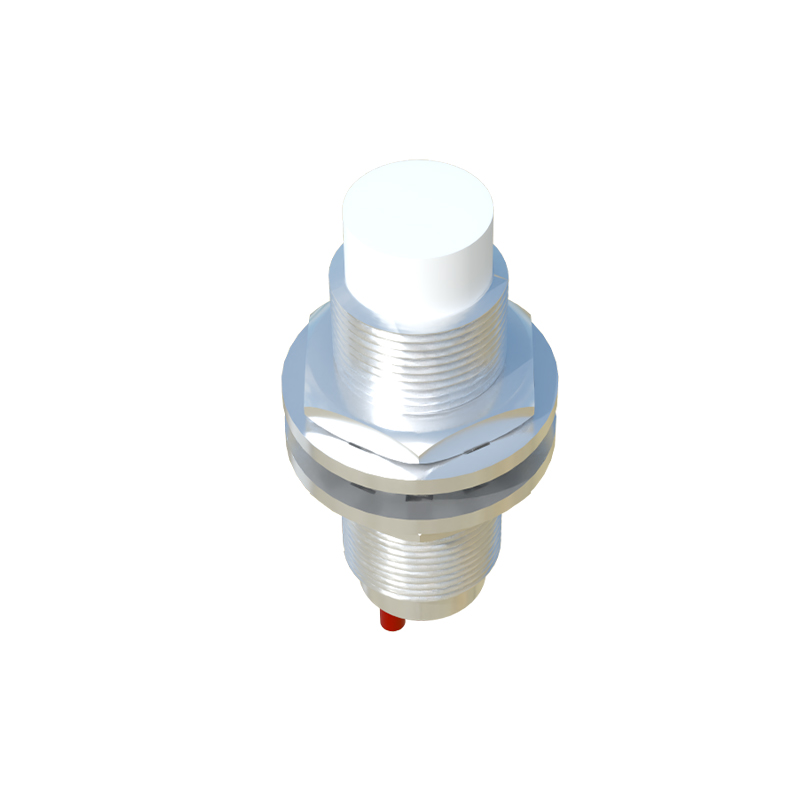
In the realm of industrial automation and control systems, proximity sensors play a pivotal role in detecting the presence or absence of objects without physical contact. Among these, universal proximity sensors are widely favored for their versatility across various applications, including manufacturing lines, robotics, and safety systems. This article delves into the schematic diagram of a universal proximity sensor, elucidating its core components, operational principles, and typical circuit configurations to provide a comprehensive understanding for engineers and technicians.
A universal proximity sensor typically operates based on electromagnetic, capacitive, or inductive principles, with inductive types being the most common in industrial settings due to their reliability with metallic targets. The schematic diagram of such a sensor reveals several key sections: the oscillator circuit, detection circuit, output stage, and power supply unit. At the heart of the sensor is the oscillator, which generates a high-frequency electromagnetic field from a coil (L1) connected to a capacitor (C1) in a resonant tank configuration. This oscillator is driven by an integrated circuit (IC) or transistor-based amplifier, often labeled as U1 or Q1 in schematics, which maintains oscillations as long as no target is within the sensing range.
When a metallic object enters the sensor's field, eddy currents are induced in the target, causing a change in the oscillator's amplitude or frequency. This alteration is monitored by the detection circuit, which usually comprises a demodulator and comparator. In the schematic, the demodulator (e.g., a diode D1 and filter capacitor C2) converts the AC signal from the oscillator to a DC voltage. This voltage is then fed into a comparator (U2), such as an operational amplifier, where it is compared against a reference voltage (Vref) set by resistors R1 and R2. If the detected voltage drops below or rises above the threshold—depending on the sensor design—the comparator triggers a state change.

The output stage translates this detection into a usable signal for control systems. Common output types include NPN or PNP transistors (Q2) for switching loads, or solid-state relays for higher current applications. In the schematic, the output transistor is often shown connected to a load resistor (RL) and protected by a flyback diode (D2) to suppress voltage spikes from inductive loads. Additionally, universal proximity sensors may feature adjustable sensing ranges via potentiometers (P1) in the oscillator or comparator sections, allowing fine-tuning for specific environments.
Power supply considerations are critical in the schematic, with most sensors designed for DC voltages (e.g., 10-30 VDC) or AC variants. A voltage regulator (U3) ensures stable operation, while capacitors (C3, C4) filter noise and decouple the supply. The schematic also includes protection elements like fuses (F1) and transient voltage suppressors (TVS diodes) to safeguard against electrical surges, enhancing durability in harsh industrial conditions.

Understanding this schematic enables engineers to troubleshoot issues, such as false triggers or reduced sensing distance, by checking component values or signal paths. For instance, a faulty oscillator coil might manifest as no oscillation, while a degraded capacitor could cause drift in sensitivity. Moreover, the universal design allows adaptation to different target materials and environments by modifying circuit parameters, making it a cornerstone in modern automation.
In summary, the schematic diagram of a universal proximity sensor encapsulates a sophisticated yet elegant interplay of electronics to achieve non-contact detection. By mastering its components—from the resonant oscillator to the robust output stage—professionals can optimize sensor performance, ensuring efficient and reliable operation in diverse applications. As technology advances, these schematics continue to evolve, integrating digital interfaces and smart features, but the fundamental principles remain rooted in electromagnetic theory and practical circuit design.