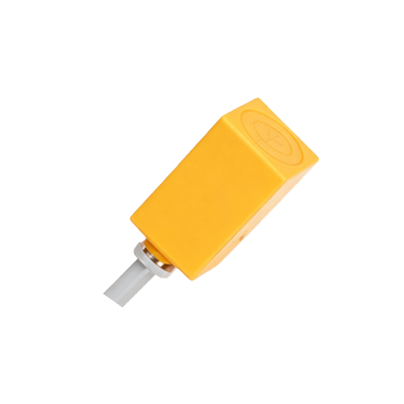
In industrial automation and control systems, the 3-wire proximity sensor is a fundamental component for detecting the presence or absence of metallic objects without physical contact. Its reliability and precision make it indispensable in applications ranging from assembly lines to robotic systems. Unlike 2-wire sensors that are simpler but have limitations in load handling and leakage current, the 3-wire design offers enhanced performance, making proper wiring crucial for optimal operation. This guide provides a detailed, industry-focused walkthrough on wiring a 3-wire proximity sensor, ensuring safety, efficiency, and compliance with standard practices.
First, it's essential to understand the basic configuration of a 3-wire proximity sensor. Typically, these sensors come with three distinct wires: brown, blue, and black. The brown wire is designated for the positive supply voltage (often labeled as V+ or +V), which usually connects to a DC power source ranging from 10 to 30 VDC, depending on the sensor model. The blue wire serves as the negative or ground connection (labeled as V- or 0V), linking to the common ground of the power supply. The black wire is the output signal wire, which carries the switching signal to the control device, such as a PLC (Programmable Logic Controller) or relay. Some sensors may have alternative wire colors like white for output or additional functions, so always refer to the manufacturer's datasheet to confirm specifications.
Before starting the wiring process, prioritize safety by disconnecting all power sources to prevent electrical shocks or equipment damage. Gather necessary tools, including a screwdriver, wire strippers, and appropriate connectors. Verify the sensor's operating voltage and current ratings, as mismatched parameters can lead to malfunction or failure. For instance, connecting a 12 VDC sensor to a 24 VDC supply may cause permanent damage. Additionally, ensure the load (e.g., a PLC input or relay coil) is compatible with the sensor's output type—whether it's NPN (sinking) or PNP (sourcing). NPN sensors switch the negative side of the load, common in Asian and European systems, while PNP sensors switch the positive side, often used in North America.
To wire the sensor, begin by preparing the power supply. Connect the brown wire to the positive terminal of the DC power source and the blue wire to the negative terminal. Use secure terminals or connectors to avoid loose connections, which can cause intermittent faults. For the output, link the black wire to the input of the control device. If using an NPN sensor, connect the black wire to the PLC input, and ensure the PLC's common is tied to positive voltage. For a PNP sensor, connect the black wire to the PLC input with the common connected to ground. Always include a protective fuse in the power line, rated slightly above the sensor's maximum current, to safeguard against short circuits. Route wires away from high-voltage cables or sources of electromagnetic interference to prevent signal noise, which can trigger false readings.
After wiring, perform thorough testing to validate the installation. Re-apply power and observe the sensor's indicator LED, which typically lights up when powered and may blink or change state upon detecting a target. Use a multimeter to check voltage levels: between brown and blue wires, it should match the supply voltage (e.g., 24 VDC), and the black wire should show a voltage shift (e.g., from 0V to 24V for PNP) when the sensor activates. Introduce a metal target within the sensing range to verify the output signal triggers the control device as expected. If issues arise, double-check connections for polarity errors, ensure the load isn't exceeding the sensor's capacity, and confirm the sensing distance aligns with the target material—ferrous metals generally have longer ranges than non-ferrous ones.
In summary, wiring a 3-wire proximity sensor involves careful attention to wire colors, power specifications, and output configurations. By adhering to these steps, engineers can achieve reliable sensor integration, minimizing downtime and enhancing system performance. Regular maintenance, such as inspecting for wear or contamination, further ensures long-term operation. As technology evolves, always stay updated with manufacturer guidelines to leverage advancements in sensor design and functionality.