Assembling a laser sensor for industrial use requires precision, an understanding of optical and electronic components, and adherence to safety protocols. This guide outlines a systematic approach for engineers and technicians to ensure reliable sensor performance in demanding environments such as manufacturing, automation, and quality control.
Before beginning assembly, gather all necessary components and tools. Essential parts typically include the laser diode module, photodetector (often a photodiode or position-sensitive device), lens assembly, housing unit, driver circuit board, power supply connectors, and mounting brackets. Required tools consist of anti-static wrist straps, precision screwdrivers, tweezers, a soldering iron with fine tip, multimeter, optical alignment jigs, and a clean, well-lit workspace. Always wear appropriate personal protective equipment (PPE), including laser safety goggles rated for the specific wavelength of your laser diode, to prevent accidental exposure to harmful radiation.
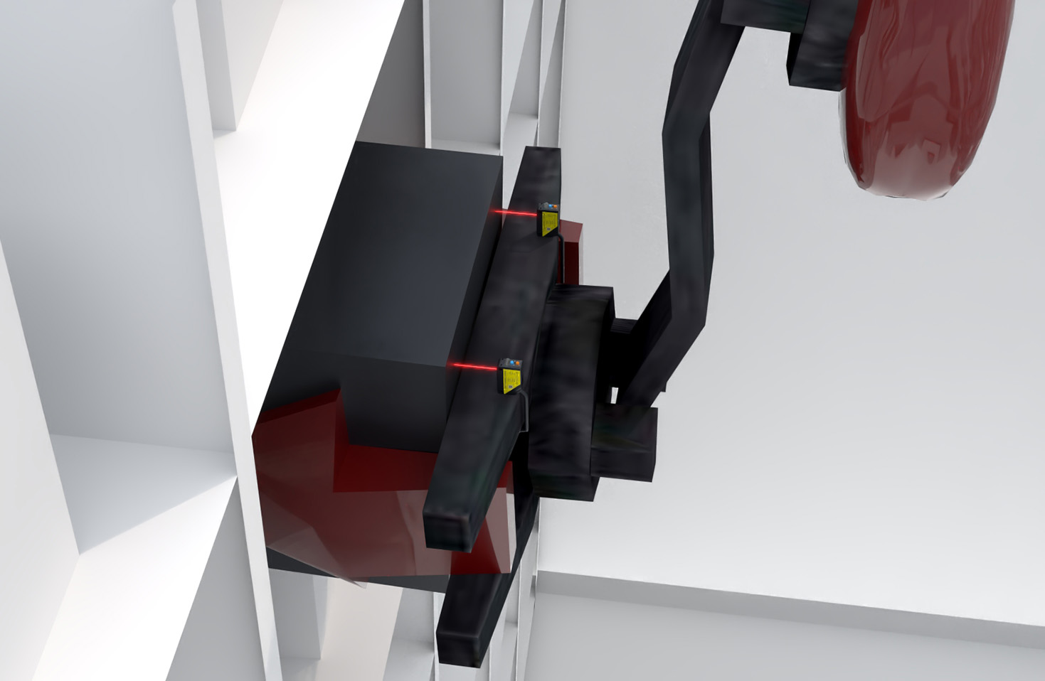
Start by preparing the housing. Inspect the sensor housing for any defects or debris that could affect alignment or sealing. Many industrial housings are made from anodized aluminum for durability and thermal stability. Install any provided gaskets or O-rings if the sensor requires an IP (Ingress Protection) rating for dust and moisture resistance. Secure the mounting brackets according to the intended installation angle and position.
Next, focus on the laser emitter assembly. Carefully unpack the laser diode module, handling it only by its edges to avoid contamination. Using an anti-static wrist strap, solder the driver circuit board to the laser diode's leads. The driver circuit is critical for providing stable current and preventing power surges that can instantly destroy the diode. Follow the manufacturer's datasheet for specific voltage and current requirements. Once soldered, use a multimeter to verify the connections and test the driver output without the diode connected. After confirmation, temporarily power the circuit to check the laser's basic operation on a low setting, ensuring the beam is emitted.
Now, proceed to the optical alignment stage, which is the most delicate part of the process. Place the laser diode module into its designated slot in the housing. Install the collimating lens or lens assembly in front of the diode. The goal is to produce a straight, focused beam with minimal divergence. Use optical alignment jigs or a beam profiler if available. Adjust the lens position meticulously using tweezers or adjustment screws until the beam profile is clean and the spot size at the target distance meets specifications. For sensors measuring distance or displacement, this alignment is paramount. Once satisfied, secure the lens assembly with thread-locking adhesive or set screws, taking care not to shift the alignment.
The receiver side assembly follows. Install the photodetector (e.g., a PIN photodiode) in its opposing housing compartment. Solder its connections to the signal processing board, which amplifies and conditions the weak electrical signal generated when the laser light is reflected back to the detector. Ensure the detector is oriented correctly to receive the returning beam. For triangulation-based sensors, the angle between the laser emitter and detector is fixed and must not be altered.
Integration and wiring come next. Place the assembled emitter and receiver units into the main housing. Connect the power supply lines and any output signal cables (e.g., analog 4-20mA, digital IO, or serial communication like RS-485) to the main processing board. Route wires neatly to avoid strain and use cable glands for external connections to maintain the housing's IP rating. Double-check all electrical connections against the wiring diagram.
Before final sealing, conduct preliminary tests. Power the sensor and use a calibrated target at a known distance. Observe the output signal on an oscilloscope or data acquisition system. Verify key parameters: sensing range, linearity, repeatability, and response time. Adjust potentiometers on the processing board if necessary for offset or gain. Test under different ambient light conditions if applicable.
Finally, seal the housing completely using the provided screws. For high-vibration environments, consider applying thread locker. Attach any external labels indicating model number, laser class, power requirements, and warning symbols.
Post-assembly, perform a full calibration and validation. Use standard calibration artifacts relevant to the sensor's application, such as gauge blocks for distance or standardized reflective surfaces. Document all test results. Regular maintenance checks should include cleaning the optical windows with approved lens cleaners and inspecting for physical damage.
Proper assembly ensures the laser sensor delivers accurate, stable measurements, crucial for tasks like precision positioning, edge detection, and thickness measurement. Always refer to the specific manufacturer's instructions, as designs can vary significantly.