Proximity sensors are ubiquitous in modern automation, serving as the silent sentinels of industrial control systems. Programming these devices effectively is not merely a coding exercise; it is an integration of hardware understanding, logic design, and application-specific tuning. This guide outlines a practical, step-by-step methodology for engineers to implement and program proximity sensors, focusing on inductive and capacitive types commonly found in factory environments.
The journey begins long before writing the first line of code. It starts with sensor selection and physical installation. An inductive sensor, ideal for detecting metallic objects, must be chosen with the correct sensing range, factoring in a safety margin of approximately 70-80% of the rated distance to account for material variations and environmental factors. For non-metallic targets like glass, wood, or liquids, a capacitive sensor is required. Mounting is critical; ensure the sensor face is parallel to the target's approach path and free from obstructions. Nearby metal structures or other sensors can cause interference, necessitating adequate spacing.
Wiring forms the physical bridge to the controller. Most modern 3-wire DC sensors (PNP or NPN) connect to a Programmable Logic Controller (PLC) digital input module. The standard wiring configuration involves connecting the brown wire (typically +24V DC) to the positive supply, the blue wire to the common negative (0V), and the black (or white) output wire to the PLC input terminal. Always consult the datasheet. A correctly wired sensor will often have a diagnostic LED that illuminates when a target is detected.
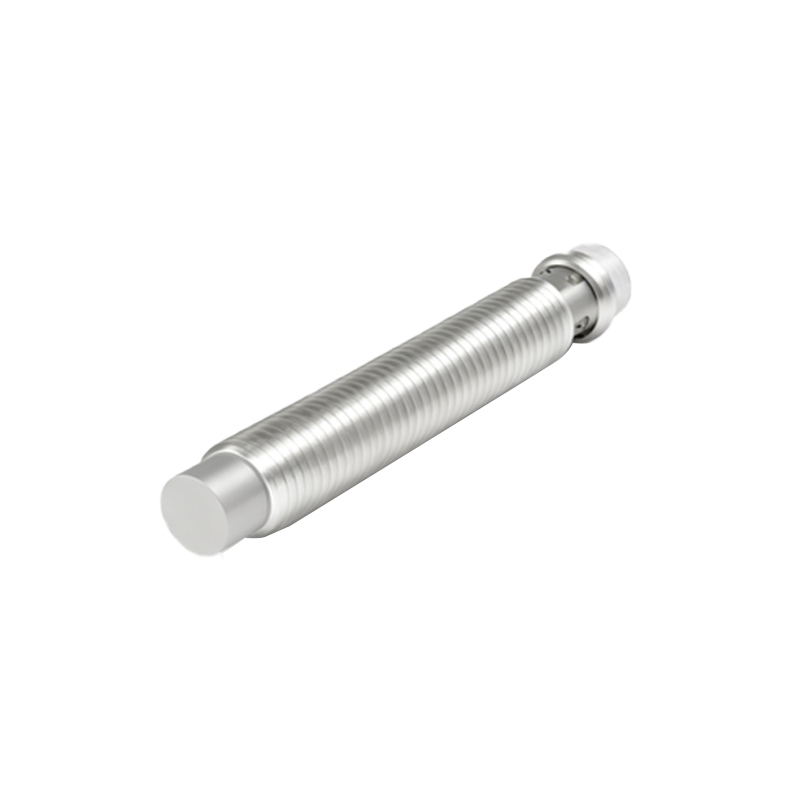
The core programming logic within the PLC is elegantly simple. The sensor's physical state is mapped to a memory bit, often called an input tag (e.g.,I0.0 orSensor_1_In). This bit becomesTRUE or1 when a target is within the sensing range andFALSE or0 otherwise. This binary signal is the fundamental building block for all subsequent logic.
However, robust industrial programming requires moving beyond this basic read. Debouncing is an essential technique. Mechanical vibration or target flutter can cause the sensor signal to oscillate rapidly between on and off states. Implementing a timer-based delay in your PLC logic prevents these false triggers. For instance, a timer can be programmed to only confirm a detection if the sensor input remains active for a sustained period, such as 50 milliseconds. Conversely, a similar delay can confirm an object's absence.
Integrating the sensor into the machine's control sequence is the next step. A common application is part positioning on a conveyor. The sensor detects a part's arrival (Sensor_In = TRUE), triggering a timer to allow for precise positioning before activating a stopper cylinder or a robotic pick command. The ladder logic or structured text would sequence these actions, using the sensor input as the primary trigger condition.
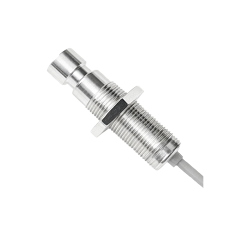
For counting applications, the programming utilizes the positive edge (rising edge) of the sensor signal. Each time the sensor changes from off to on, a counter instruction is incremented. It is crucial to reset the counter appropriately, typically at the start of a new batch via a operator panel command or a master reset signal.
Advanced tuning is often necessary for optimal performance. Many sensors feature a potentiometer for sensitivity adjustment. For a capacitive sensor detecting a plastic bottle, the sensitivity must be set high enough to see the bottle but low enough to ignore the background conveyor belt. This is often an iterative process: adjust, test with the actual target, and observe. Some digital sensors offer teach-in functions via a push-button or via IO-Link communication, allowing for automated parameter setting and remote diagnostics.
Troubleshooting is a vital programming-adjacent skill. A systematic approach saves time. First, verify power and wiring. Next, observe the sensor's built-in LED independently of the PLC program. If the LED activates correctly with a target but the PLC input does not, the issue lies in the wiring to the PLC module or the module's configuration. If the LED behaves erratically, re-evaluate the installation environment for electrical noise, cross-talk from adjacent sensors, or an incorrect sensing distance. PLC programming can include diagnostic routines that log sensor activation faults or count error rates for predictive maintenance.
Finally, documentation completes the process. Annotate the PLC program with clear comments explaining the purpose of each sensor (e.g., "Carton Presence at Station 3"). Maintain a sensor list in the electrical drawings correlating the part number, PLC address, and its function. This practice is invaluable for future troubleshooting and system modifications.
Successful proximity sensor programming is therefore a holistic discipline. It demands careful hardware setup, the implementation of stable and logical control routines, and a thorough understanding of the sensor's operational characteristics within its specific application context. By following this structured approach, engineers can ensure reliable, maintainable, and efficient automated systems