In industrial automation and control systems, proximity sensors play a crucial role in non-contact detection of metallic or non-metallic objects. Among the various types available, the 3-wire DC proximity sensor is one of the most common and reliable configurations used in machinery, conveyor systems, and safety applications. This article provides a detailed, practical guide to understanding 3-wire proximity sensor wiring diagrams, ensuring correct installation and optimal performance.
A standard 3-wire DC proximity sensor typically consists of three distinct wires, each color-coded for easy identification according to international standards (though colors can vary by manufacturer). The most common configuration is: a brown wire for the positive DC supply voltage (V+), a blue wire for the negative DC supply or common ground (0V or V-), and a black wire for the output signal. The output can be either NPN (sinking) or PNP (sourcing), which determines how the sensor interfaces with the programmable logic controller (PLC) or other control devices. Understanding this distinction is fundamental.
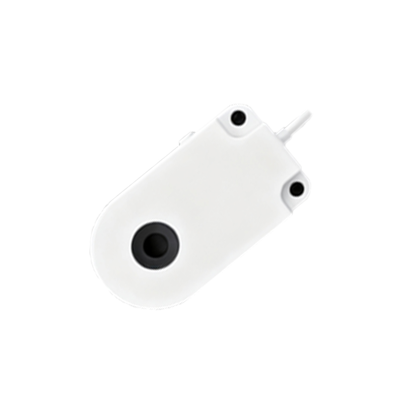
Let's examine the wiring diagram for an NPN-type 3-wire sensor. In this setup, the brown wire connects to the positive terminal of the DC power supply (commonly 10-30V DC). The blue wire connects to the negative terminal of the same power supply. The black output wire is connected to the input channel of the PLC. When the sensor detects a target within its sensing range, the NPN transistor inside the sensor switches ON, allowing current to flow from the PLC input, through the sensor's black wire, and out through the blue wire to ground. This effectively "sinks" the current to ground, creating a low signal at the PLC input. The PLC input module must be compatible with this sinking signal, typically requiring a common positive connection.
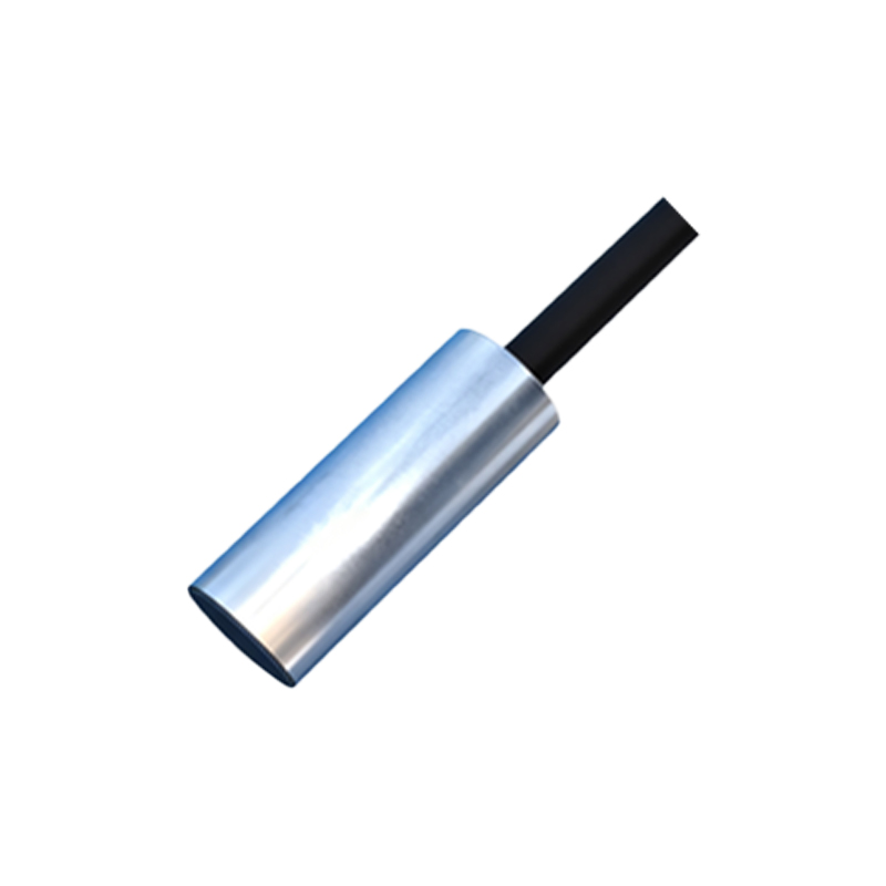
Conversely, for a PNP-type 3-wire sensor, the wiring for power remains identical: brown to positive, blue to negative. However, the function of the black output wire changes. When activated, the internal PNP transistor switches, allowing current to flow from the positive supply (through the sensor) out via the black wire to the PLC input. This "sources" current to the PLC, creating a high signal. The PLC input for a PNP sensor usually has a common negative connection. Misidentifying the sensor type and wiring it to an incompatible PLC input is a frequent installation error that leads to malfunction.
A clear wiring diagram visually represents these connections. It often includes symbols for the DC power supply, the sensor, the load (PLC input), and sometimes a protective fuse. The diagram shows the exact termination points. For instance, in a typical NPN sensor diagram, you would see lines connecting: Power Supply (+) -> Brown Wire; Power Supply (-) -> Blue Wire; Black Wire -> PLC Input Terminal; and a separate line from the same PLC Input Terminal to the Power Supply (+) to complete the circuit through the PLC's internal circuitry. This forms a complete loop when the sensor activates.
Several critical best practices must be followed during installation. First, always verify the sensor's specifications—operating voltage, output type (NPN/PNP), and current rating—against the power supply and controller requirements. Second, ensure proper grounding. The power supply's negative terminal and the sensor's blue wire should be connected to a clean, stable ground point to minimize electrical noise, which can cause false triggering. Third, consider using shielded cables in environments with high electromagnetic interference (EMI), connecting the shield to ground at only one end to prevent ground loops. Fourth, for long cable runs, account for voltage drop; using a wire gauge that is too thin can reduce the voltage at the sensor below its operational minimum.
Troubleshooting common wiring issues often starts with the diagram. If a sensor fails to trigger, check: 1) Power presence between brown (+) and blue (-) wires with a multimeter. 2) Correct output type (NPN/PNP) match with the controller. 3) Continuity and integrity of all connections. A sensor with a normally open (NO) output should show supply voltage on the black wire when inactive (for PNP) or near 0V (for NPN), switching when a target is presented. Many modern sensors feature an LED indicator that lights when powered and may blink or change state upon detection, providing immediate visual feedback.
In summary, correctly interpreting and implementing a 3-wire proximity sensor wiring diagram is essential for system reliability. By understanding the roles of the brown (power), blue (ground), and black (output) wires, and the critical difference between NPN (sinking) and PNP (sourcing) outputs, engineers and technicians can ensure seamless integration into automated systems, reducing downtime and