In the realm of industrial automation and control systems, proximity magnetic switch sensors stand as fundamental components for non-contact detection and position sensing. While technical datasheets provide the essential specifications, a detailed examination of sensor images offers invaluable, practical insights for engineers during selection, integration, and troubleshooting. This article delves into the visual characteristics and functional clues revealed by high-quality photographs of these ubiquitous devices.
A primary visual distinction lies in the housing form factor. Images clearly showcase the two predominant styles: cylindrical (barrel-type) and rectangular (block-type) housings. Cylindrical sensors, often with threaded metal bodies (e.g., M8, M12, M18, M30), are designed for easy mounting in drilled holes, providing robust mechanical stability. Close-up images reveal key details like the sensing face material (often PBT or metal), the IP (Ingress Protection) rating indicated by sealing design, and the orientation of the electrical connection—be it axial (cable outlet at the back) or radial (cable outlet from the side). Rectangular housings, typically molded from robust plastics like PPS or PA, may feature integrated mounting brackets or slots. Images of these units highlight their compact design for space-constrained applications and often show the labeling for sensing range and output type.
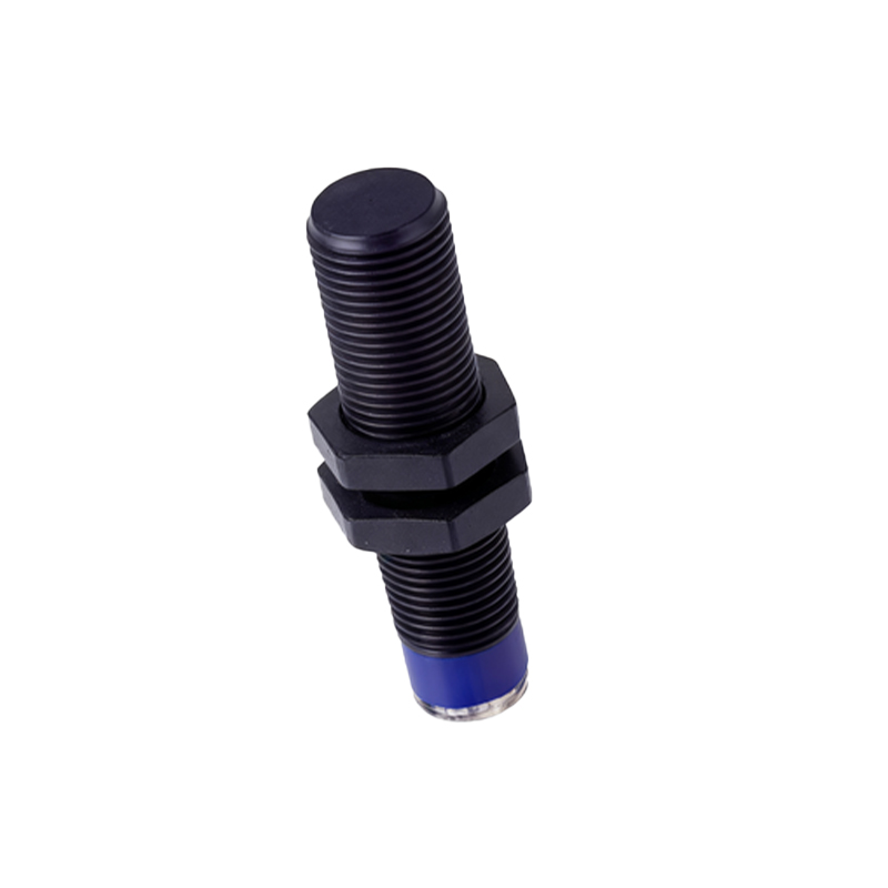
The electrical connection interface is another critical aspect visible in sensor imagery. For sensors with pre-attached cables, images show the cable type (PVC or PUR sheathing), length, and the connector at the distal end, such as a molded M12 or M8 connector. For sensors with terminal connections, clear photos display the terminal block, often with markings for the supply voltage (V+), ground (0V), and the output signal line. The color-coding of wires—brown for V+, blue for 0V, and black for the switching output—is a universal visual cue confirmed through imagery. Some advanced models feature LED indicators; a well-composed image will show the position and typical color (often red or green) of this status LED, which is crucial for visual confirmation of operational state and diagnostic purposes.
Internally, while not always visible in standard product photos, cutaway or exploded-view images are exceptionally informative. They illustrate the core components: the permanent magnet (in the target), the reed switch or magneto-resistive element housed within the sensor body, and the associated conditioning electronics. Seeing the spatial relationship between the sensing element and the housing face helps engineers understand the effective sensing window and potential blind spots. Images depicting the switching mechanism in operation—showing the reed contacts closing or the IC's state change in response to a magnetic field—provide an intuitive grasp of the working principle far beyond textual description.
Contextual application images are perhaps the most practical. Photographs showing a magnetic proximity sensor installed on a linear actuator, detecting the position of a piston via a ring magnet, immediately convey mounting orientation and typical sensing distances. Images in conveyor system applications demonstrate how sensors are mounted to detect metallic or magnetized objects on a moving belt. These visuals address real-world considerations like mounting clearance, potential interference from adjacent metal structures, and the alignment between the sensor and the target magnet. For cylinder position sensing, a series of images showing sensors mounted on the cylinder body and the corresponding magnetic piston positions offer a clear tutorial on implementation.
Furthermore, images can highlight special features and variants. Pictures of sensors with extended sensing ranges, often with a longer or more prominent sensing head, are easily distinguishable. Images of analog output sensors might be visually similar, but attention to labeling is key. Ruggedized versions for heavy-duty environments are shown with thicker housings, metal guards, or special coatings. Contrasting images of Normally Open (NO) and Normally Closed (NC) types, while visually identical, underscore the importance of consulting the schematic symbol on the housing label.
In conclusion, a meticulous analysis of proximity magnetic switch sensor images is a powerful complementary tool to datasheet analysis. From housing geometry and connection details to internal anatomy and application context, visual information accelerates correct product selection, ensures proper mechanical and electrical integration, and aids in swift field diagnostics. Engineers are encouraged to leverage high-resolution images from manufacturer catalogs and technical resources to build a robust visual lexicon for these critical sensing devices.