In the realm of industrial automation and precision sensing, the V20 series proximity light sensor is renowned for its reliability in detecting object presence and distance without physical contact. However, even the most robust components can encounter operational hurdles. A common and critical issue faced by engineers and maintenance technicians is calibration failure. This comprehensive guide delves into the root causes, diagnostic procedures, and corrective actions for V20 proximity light sensor calibration failures, ensuring optimal system performance and minimal downtime.
Calibration is the cornerstone of sensor accuracy. For a V20 proximity sensor, this process involves setting the correct threshold values for light reception to distinguish between the presence and absence of a target object within its specified sensing range. When calibration fails, the sensor may exhibit erratic behavior: false triggering, failure to detect valid targets, or inconsistent readings. This directly impacts automated processes, leading to production errors, machine stoppages, and potential safety concerns.
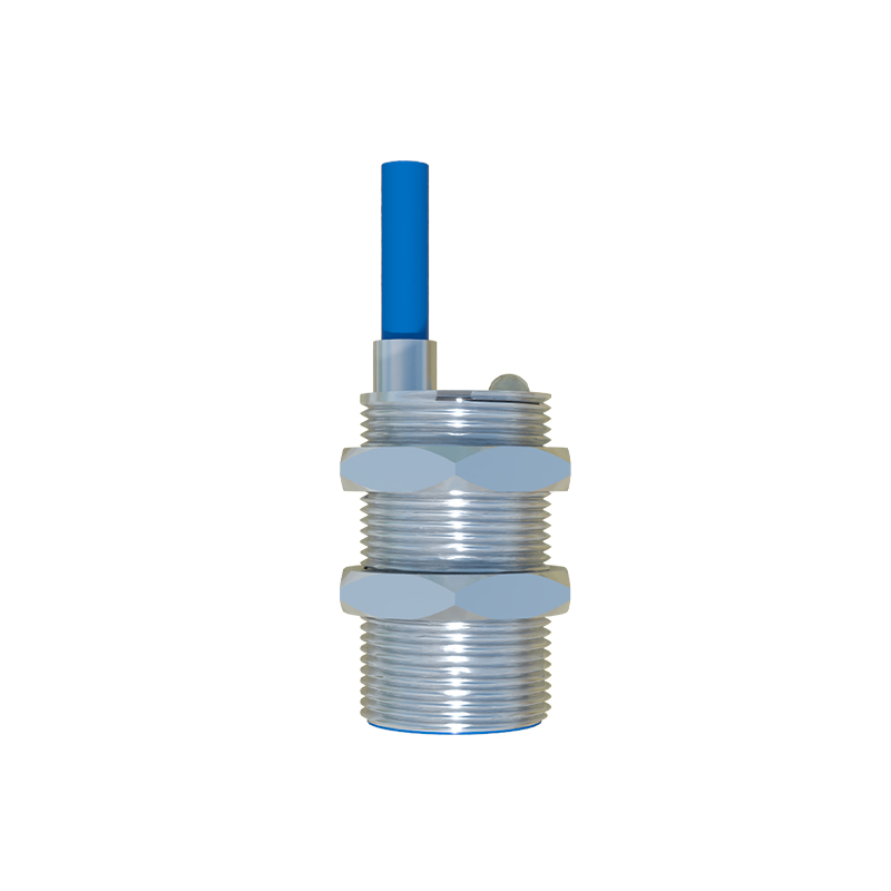
The etiology of calibration failure is multifaceted. A primary suspect is environmental contamination. Dust, oil mist, or chemical residues accumulating on the sensor's lens can significantly attenuate or scatter the emitted and received light beams. This alters the light intensity profile, making the established calibration parameters invalid. Regular inspection and cleaning of the lens with appropriate, non-abrasive materials are essential preventive measures.
Secondly, electrical and signal integrity issues are frequent culprits. Inadequate or unstable power supply voltage falling outside the sensor's specified operating range (commonly 10-30V DC for many V20 models) can prevent the internal circuitry from functioning correctly during calibration. Similarly, electromagnetic interference (EMI) from nearby high-frequency drives, motors, or welding equipment can induce noise in the signal lines, corrupting the calibration data. Ensuring proper shielding, using twisted-pair cables, and installing ferrite cores on cables near noise sources are effective countermeasures. Additionally, verify all connections for tightness and corrosion, paying close attention to the grounding point, as a poor ground can lead to reference voltage drift.
Thirdly, mechanical misalignment or target-related problems can cause calibration to fail. The sensor must be correctly aligned perpendicular to the target surface for optimal reflectance. Even a slight angular deviation can reduce the effective signal strength. Furthermore, the calibration procedure is highly dependent on the target's characteristics—its color, material, and surface finish. Attempting to calibrate with a target that has different reflective properties than the actual application targets will result in a failed or ineffective calibration. Always use the correct, representative target specified in the sensor's manual during the calibration routine.
Internal component degradation is another potential cause. Over time, the LED light source within the sensor can experience lumen depreciation, emitting less light than its original specification. The phototransistor or photodiode receiver may also lose sensitivity. This gradual aging shifts the sensor's operational curve, making previous calibration settings obsolete and new calibration attempts challenging. If the sensor is old or has been in continuous service, component wear should be considered.
The diagnostic approach should be systematic. Begin with a visual inspection for contamination and physical damage. Next, use a multimeter to confirm the power supply voltage at the sensor's terminals under load. Monitor the voltage for stability. Observe the sensor's output indicator LED (if available) during a calibration attempt. Many V20 sensors provide specific flashing patterns that indicate calibration success, failure, or error conditions; consult the product datasheet for these codes.
For advanced troubleshooting, an oscilloscope can be invaluable. Probe the output signal line to check for a clean, stable switching waveform free from excessive noise or ringing. If possible, temporarily relocate the sensor to a clean, electrically quiet bench setup with a known-good power supply and a standard target. Attempt calibration in this controlled environment. Success here points to an external issue (environment, power, EMI, installation). Persistent failure strongly suggests an internal sensor fault.
Corrective actions follow diagnosis. For environmental issues, implement a cleaning schedule and consider protective housings. Address power issues with regulated power supplies and proper wiring. Mitigate EMI through improved layout, shielding, and filtering. Re-align the sensor meticulously and use the correct target. If internal failure is confirmed, and the sensor is outside its performance window, replacement is the most reliable solution. Before replacing, ensure you have the latest firmware/software for the sensor's configuration tool, as updates sometimes resolve known calibration bugs.
In conclusion, V20 proximity light sensor calibration failure is a solvable problem with a methodical approach. Understanding the interplay between environmental conditions, electrical integrity, mechanical setup, and sensor health is key. By adhering to rigorous installation practices, performing preventative maintenance, and executing structured troubleshooting, engineers can swiftly restore sensor functionality, ensuring the continued precision and efficiency of the automated systems they support. Always prioritize consulting the official manufacturer's documentation for model-specific instructions and tolerances.