In industrial automation and control systems, proximity sensors are fundamental components for non-contact detection of objects. They provide critical data for machine sequencing, positioning, counting, and safety interlocks. A failure to read data from a proximity sensor can lead to production line stoppages, quality defects, or even safety hazards. This article outlines a systematic approach to diagnosing and resolving common causes of proximity sensor data read failures, adhering to standard industrial troubleshooting practices.
The initial step when a sensor appears unresponsive is to verify the most basic elements: power and physical connections. Ensure the sensor is receiving the correct supply voltage as per its datasheet (e.g., 10-30V DC for a typical PNP/NPN sensor). Use a multimeter to check voltage at the sensor's power terminals. Loose connections, corroded terminals, or damaged cables are frequent culprits. Inspect the cable along its entire length for pinch points, cuts, or exposure to excessive heat or chemicals. The connector, often a M8 or M12 type, should be securely fastened and free from debris or moisture ingress.
Assuming power is present, the next phase involves the sensor's output signal. First, determine the sensor type: PNP (sourcing) or NPN (sinking). A common mistake is wiring a PNP sensor to an NPN-compatible input module, or vice-versa, resulting in no signal. Check the wiring diagram against the PLC or controller input specifications. With power applied, observe the sensor's indicator LED (if equipped) when a target is presented. A lit or blinking LED typically indicates the sensor is detecting the target internally, suggesting the issue lies downstream in the signal path.
If the indicator does not activate, the problem is likely with the sensor itself or its environment. Key sensor-specific issues include:
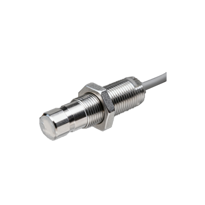
1. Incorrect Sensing Distance: The target may be outside the sensor's nominal sensing range. Consult the datasheet for the precise sensing distance, which can be reduced for non-standard materials (e.g., aluminum versus steel).
2. Target Material, Size, and Orientation: Inductive sensors require ferrous metal targets. Capacitive sensors detect a wider range of materials but are sensitive to environmental changes. The target must be large enough and approach the sensor face correctly.
3. Sensor Deterioration or Damage: The sensing face may be coated with dirt, grease, or metal shavings, blocking detection. Physical impact can damage internal components. In harsh environments, prolonged exposure to welding spatter, coolants, or extreme temperatures can cause premature failure.
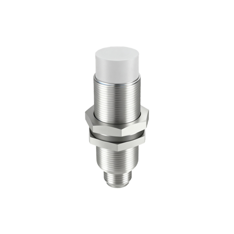
4. Electrical Noise Interference: In facilities with variable frequency drives (VFDs), motors, or welding equipment, electromagnetic interference (EMI) can disrupt sensor operation. Symptoms can be intermittent. Ensure sensor cables are shielded, and the shield is properly grounded at one end. Route sensor cables away from power lines. Using ferrite cores on the cable near the sensor can suppress high-frequency noise.
For sensors with an active indicator but no signal at the controller, focus on the signal wiring and the input module. Use the multimeter to measure the voltage between the sensor's signal wire and the common (0V) when a target is present. For a 24V DC PNP sensor, you should read approximately 24V. If the voltage is present at the sensor but not at the PLC terminal, there is a break in the signal wire. Also, verify that the PLC input point is not faulty by temporarily swapping with a known-working input (ensure voltage compatibility first). Check the input module's status LEDs for indications.
Configuration errors in the control system can also manifest as a "no data" issue. Some advanced sensors with IO-Link or analog outputs require parameter configuration. Ensure the correct data type (e.g., discrete, byte, word) is mapped in the PLC program. A programming error, such as addressing the wrong input memory location, will also prevent data read.
Finally, do not overlook the mechanical aspects. Vibration can loosen sensor mounts, altering the critical gap between the sensor and the target. Repeated impacts from the target can physically damage the sensor face. Ensure the sensor is securely mounted and properly aligned.
A methodical approach—starting with power and connections, moving to the sensor and its environment, then to the wiring and controller—will efficiently isolate the root cause of proximity sensor data failure. Keeping spare sensors on hand and maintaining a log of failures and environmental conditions aids in predictive maintenance and reduces future downtime.