As an experienced electrical engineer, I often encounter questions about diagnosing industrial sensors. Proximity sensors are critical components in automation and control systems, detecting the presence or absence of an object without physical contact. When a sensor malfunctions, it can halt production lines or cause erratic machine behavior. Using a digital multimeter (DMM) is a fundamental and effective method for preliminary fault-finding. This guide provides a systematic approach to testing inductive and capacitive proximity sensors, which are the most common types in industrial settings.
Before testing, ensure safety: disconnect power to the sensor circuit whenever possible. If live testing is necessary, follow all lockout-tagout (LOTO) procedures and use appropriate personal protective equipment (PPE). Gather your tools: a reliable digital multimeter capable of measuring DC voltage, resistance (ohms), and continuity; the sensor's datasheet; and a known metal target (for inductive types) or material (for capacitive types).
First, perform a visual inspection. Check for physical damage, corrosion, loose wiring, or contamination on the sensing face. Many failures stem from environmental factors like coolant ingress or mechanical impact.
For a basic power supply check, reconnect power to the sensor's circuit. Set your multimeter to DC voltage (typically 10-30V DC for standard sensors). Identify the wiring: most 3-wire sensors have brown (V+), blue (V- or common), and black (output) wires. Refer to the datasheet for confirmation, as colors can vary. With the probes, measure between the brown (positive) and blue (negative) wires. You should read the nominal supply voltage (e.g., 24V DC). A significantly low or zero reading indicates a problem with the power supply or wiring, not necessarily the sensor itself.
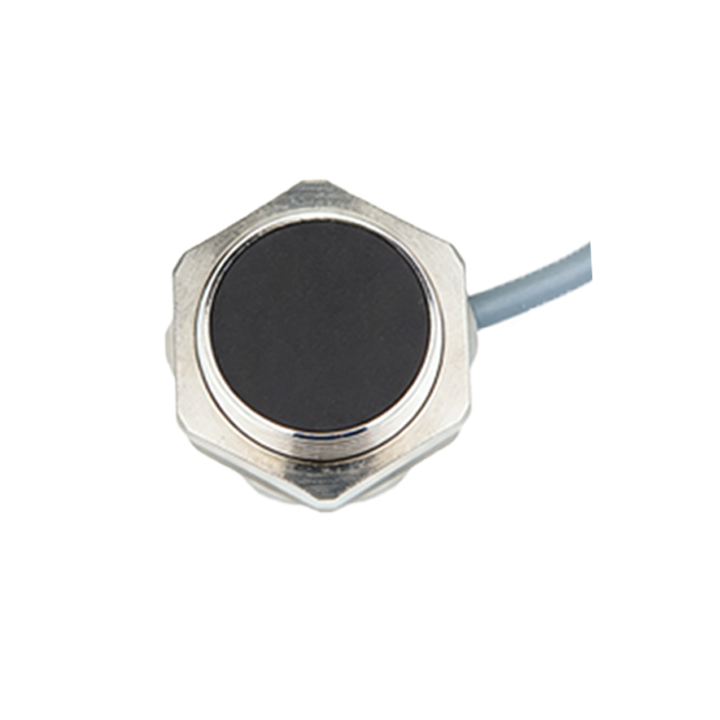
Next, test the sensor's output. The output can be NPN (sinking) or PNP (sourcing). For a PNP sensor (sourcing), the black wire outputs positive voltage when activated. With power on and no target present, measure voltage between the black output wire and the blue common wire. It should be near 0V (OFF state). Then, introduce the correct target to the sensor's sensing face. The voltage should now read close to the supply voltage (e.g., 24V) as the sensor switches ON. For an NPN sensor, the black wire sinks current to common; the behavior is opposite. You can also test the output in continuity or diode mode (power off) for a basic check of the output transistor, but the live voltage test is more definitive.
Resistance testing can reveal internal issues. Disconnect the sensor completely from power. Set the multimeter to resistance (ohms) mode. Measure between the blue (common) and black (output) wires. You should typically see a very high resistance (often over 1 MΩ), indicating the output transistor is open. Specific values depend on the sensor; consult the datasheet. Some internal failures, like a shorted transistor, will show very low resistance here. You can also measure between brown (V+) and blue (V-); a direct short here usually indicates a catastrophic internal failure.
For a more functional test, especially if the sensor seems unresponsive, simulate its operation. Connect the sensor to its correct power supply on a bench. Connect an appropriate load (like a pilot light or relay coil rated for the sensor's output) between the output wire and common. When you bring a target close, the load should activate. This confirms the entire switching function.
Remember, a multimeter test is a go/no-go diagnostic. It can identify complete failures, wiring issues, or power problems. However, it may not detect subtle issues like reduced sensing range, temperature sensitivity, or intermittent switching. For those, an oscilloscope to monitor the switching waveform or a calibrated target at a specified distance is required. Always cross-reference your findings with the manufacturer's datasheet for specific voltage drops, leakage currents, and test procedures. Proper troubleshooting with a multimeter can quickly isolate a faulty sensor, minimizing downtime and ensuring robust system operation.