In industrial automation and machinery, proximity sensors are indispensable components that detect the presence or absence of objects without physical contact. A common point of inquiry for maintenance technicians and engineers is the meaning behind a flashing green LED indicator on these sensors. This article delves into the standard interpretations, troubleshooting steps, and operational insights related to this specific status signal.
Firstly, it is crucial to understand that LED indicators, particularly the green light, serve as a vital communication interface between the sensor and the operator. While color coding and flash patterns can vary slightly between manufacturers and sensor models (inductive, capacitive, or photoelectric), a flashing green light most commonly signifies normal operation within a specific mode. Typically, a solid green light indicates that the sensor is powered on and has detected a target within its sensing range. Conversely, a flashing or blinking green light often denotes one of several states.
A frequent scenario is "Teach-In" or programming mode activation. Many modern programmable proximity sensors enter this mode when the setup button is pressed or via a specific sequence, indicated by a flashing green LED. This allows users to set parameters like sensing distance or output logic. The flash pattern during this state is usually a steady, rhythmic blink.
Another common interpretation is "Standby" or "Power-On, No Target" status. Some sensor designs use a slow flashing green light to show that the device is correctly powered and functional but is not currently detecting a valid target within its nominal range. This is a normal idle state, not an error. A rapid flash, however, might indicate an unstable detection scenario, such as a target hovering at the very edge of the sensing range, causing the output to toggle rapidly.
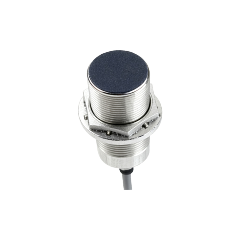
For sensors with diagnostic capabilities, a specific flash pattern—like two short flashes followed by a pause—could signal a warning. This might relate to marginal operating conditions, such as supply voltage nearing the lower limit, excessive temperature, or potential contamination on the sensing face affecting performance. It is imperative to consult the specific sensor's datasheet or manual to decode exact flash sequences.
Troubleshooting a flashing green light should follow a systematic approach:
1. Consult the Manual: Always refer to the manufacturer's documentation first. It contains the definitive guide for LED status indicators for that particular model.
2. Check Power Supply: Verify that the supply voltage (e.g., 10-30V DC) is stable and within the sensor's specified range using a multimeter. Voltage fluctuations can cause irregular LED behavior.
3. Inspect the Sensing Environment: Look for environmental factors. For inductive sensors, ensure the target material and size are appropriate. For photoelectric sensors, check for optical obstructions, dirt, or ambient light interference. For capacitive sensors, be aware of changing humidity or non-target materials influencing the field.
4. Examine Wiring and Load: Confirm correct wiring according to the datasheet (sourcing vs. sinking). Check for loose connections, short circuits, or an overload on the sensor's output. An incompatible or failing load (like a solenoid valve or PLC input) can sometimes cause feedback issues.
5. Evaluate Target Interaction: Ensure the target is entering the sensing zone correctly. The flashing might occur if the target is misaligned, too small, or moving at an inconsistent speed, causing intermittent detection.
6. Perform a Reset: If applicable, power cycle the sensor or use the reset procedure outlined in the manual to clear any temporary fault states.
Understanding these indicators enhances predictive maintenance and reduces downtime. A flashing green light is rarely a sign of catastrophic failure but rather a message about the sensor's operational state. Ignoring specific warning flashes, however, can lead to eventual malfunction or unreliable process signals.
In summary, the flashing green LED on a proximity sensor is a versatile status tool. While often representing normal operational modes like Teach-In or standby, it can also serve as an early warning system. Successful interpretation requires cross-referencing the pattern with official documentation and a methodical check of the electrical and physical installation. By mastering this simple visual cue, engineers and technicians can ensure optimal sensor performance, maintain system integrity, and swiftly address potential issues before they escalate into production line stoppages.