In the realm of industrial automation, laser displacement sensors have become indispensable tools for precise non-contact measurement. Their ability to deliver high-accuracy, high-speed data on position, thickness, and vibration is critical for quality control, robotics guidance, and assembly verification. However, unlocking their full potential hinges on effective programming and integration into a larger control system. This article delves into the core programming concepts and practical steps for deploying these sophisticated devices.
The programming journey begins long before writing a single line of code. It starts with sensor selection and understanding its communication protocol. Most modern laser sensors support standard industrial interfaces like Ethernet/IP, PROFINET, Modbus TCP, or simple analog voltage/current outputs. For programmable logic controller (PLC) based systems, Ethernet protocols are often preferred for their speed and data richness. Some sensors also offer dedicated software suites provided by the manufacturer (e.g., Keyence's LK-Navigator, Panasonic's HL-G1 Series software) for initial configuration, which can simplify setup significantly.
The primary programming tasks typically involve:
1. Parameter Configuration: This is the foundation. Using the sensor's built-in web interface, dedicated software, or sometimes serial commands, engineers must set key parameters. These include the measurement mode (e.g., peak, edge, or multi-peak detection for transparent objects), sampling rate, data averaging, and output range. Setting the correct reference distance (the point where the output is zeroed) and measurement range is crucial for accurate scaling.
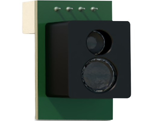
2. Data Acquisition Logic: Within the main control program (often on a PLC or industrial PC), logic must be written to request or receive data from the sensor. For network protocols, this involves establishing a connection and cyclically reading specific register addresses that hold the measurement value, status bits (like stability flags or error codes), and other diagnostics. A robust program always checks these status bits before using the measurement data to prevent errors from propagating through the system.
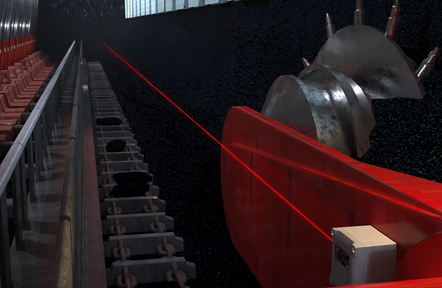
3. Data Processing and Scaling: The raw data from the sensor, often in integer counts (e.g., 0-4000 for a 4-20mA analog signal or a specific uint value for Ethernet), must be scaled into engineering units (micrometers, millimeters, or inches). This scaling function,ScaledValue = (RawValue - Offset) * Gain, is a standard piece of code in automation programs. The offset and gain are determined from the sensor's configured measurement range.
4. Triggering and Synchronization: For high-speed applications or systems with multiple sensors, external triggering is vital. Programming involves configuring the sensor to take a measurement only upon receiving a trigger signal from the PLC or a production line encoder. This ensures measurements are taken at the exact moment a part is in position, synchronizing the sensor with the machine cycle.
5. Error Handling and Diagnostics: A professional-grade program includes comprehensive error handling. This involves monitoring for communication timeouts, sensor alarm statuses (e.g., beam loss, out-of-range conditions), and implementing recovery routines. Logging these events aids in predictive maintenance and rapid troubleshooting.
Consider a simple example in structured text (ST) for a PLC, assuming a Modbus TCP sensor:
``
PROGRAM MainPLC
VAR
mbClient : MODBUS_CLIENT; // Modbus TCP client function block
rawData : INT;
scaledDistance : REAL;
sensorStatus : WORD;
CONFIG_OFFSET : REAL := 5000.0; // Example offset
CONFIG_GAIN : REAL := 0.1; // Example gain: 0.1 mm per count
END_VAR
// Execute cyclic communication
mbClient(
connect:=TRUE,
unitId:=1,
function:=MODBUS_FUNC_READ_HOLDING_REGISTER,
addr:=40001, // Starting address for measurement value
quantity:=1,
dataPtr:=ADR(rawData));
mbClient(
connect:=TRUE,
unitId:=1,
function:=MODBUS_FUNC_READ_HOLDING_REGISTER,
addr:=40010, // Starting address for status word
quantity:=1,
dataPtr:=ADR(sensorStatus));
// Check if status indicates a valid measurement (e.g., bit 0 is 1)
IF (sensorStatus AND 16#0001)<> 0 THEN
scaledDistance := (INT_TO_REAL(rawData) - CONFIG_OFFSET) * CONFIG_GAIN;
// Use scaledDistance for control logic...
ELSE
// Implement error handling: alarm, use last good value, etc.
END_IF;
``
Beyond basic measurement, advanced programming can leverage features like profile output (where the sensor sends an array of height data across a line), data buffering, and communication with higher-level MES (Manufacturing Execution Systems) for statistical process control. The trend is towards smarter sensors with embedded logic, allowing some processing (like pass/fail judgments) to be done at the sensor level, reducing PLC scan time load.
In conclusion, programming a laser displacement sensor is a systematic process that bridges hardware configuration and software logic. Success depends on a clear understanding of the sensor's capabilities, the chosen communication protocol, and the integration requirements of the automation system. Properly implemented, the programmed sensor becomes a reliable and precise data source, forming the eyes of an automated production line and ensuring consistent product quality.