In the realm of industrial automation and electrical control systems, proximity sensors are indispensable components. Their reliable operation hinges on one critical, often underemphasized, process: proper installation and connection, frequently achieved through soldering. A well-executed soldering job ensures signal integrity, mechanical stability, and long-term durability in harsh environments. This guide, tailored for electrical engineers and technicians, delves into the essential practices for soldering proximity sensors, complementing the detailed video demonstration we will reference.
Understanding the sensor's terminal structure is paramount before the iron is even heated. Most industrial proximity switches, whether inductive, capacitive, or photoelectric, feature pre-wired cables or direct solder terminals. For models with solder cups or pins, note the material. The housing is typically stainless steel or PBT plastic, but the terminals are often brass or tin-plated copper. This knowledge directly influences your choice of flux and solder. A 60/40 tin-lead solder or a lead-free alternative like SAC305 is standard, paired with a mild, activated rosin flux core or separate flux paste designed for electrical connections.
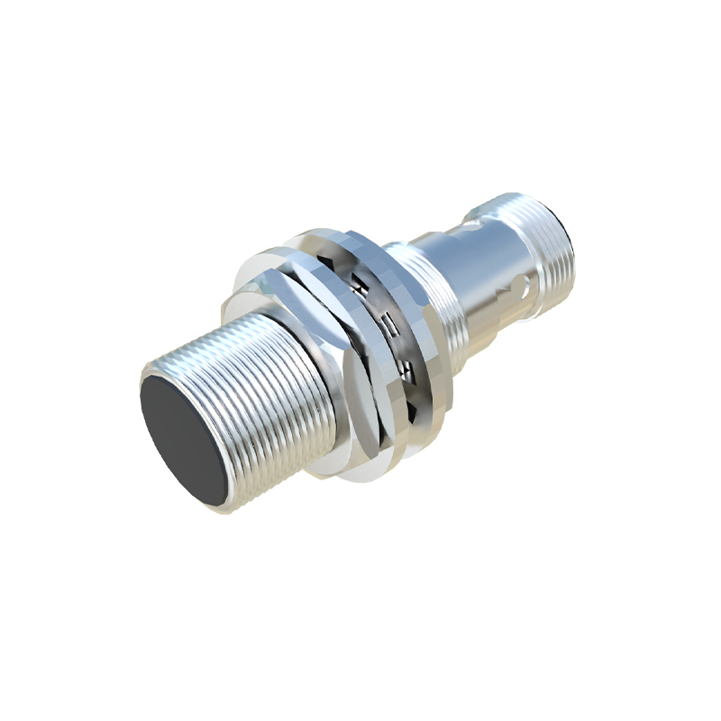
Preparation is 80% of a successful solder joint. Begin by securing the sensor in a helping hand or vise, ensuring it is stable and the terminals are accessible. If dealing with a pre-wired sensor where a cable needs replacement, carefully cut the old wire, strip the new cable jacket, and tin the individual conductor strands. Tinning involves applying a small amount of molten solder to the freshly stripped wire end, coating all strands uniformly. This step prevents fraying and ensures a quick, clean joint later. Similarly, apply a tiny amount of flux to the sensor's terminal. This cleans the metal surface and promotes optimal solder flow.
Now, for the soldering process itself, as demonstrated in the accompanying video. Set your temperature-controlled soldering station to approximately 350°C (660°F) for leaded solder or 380°C (715°F) for lead-free. The key is to apply heat to the terminal, not the solder itself. Place the tip of the iron firmly against the terminal, making good thermal contact. After 2-3 seconds, feed the solder wire into the junction between the terminal and the iron tip—not directly onto the iron. The heated terminal will melt the solder, which should flow smoothly and wick onto the surface, forming a concave fillet. For wire-to-terminal connections, hold the pre-tinned wire against the fluxed terminal, apply heat to both, and then feed solder. The joint should be shiny and smooth, resembling a small, shiny mountain slope, not a dull blob or a spiky ball. A cold solder joint—dull, grainy, and poorly bonded—is a primary source of intermittent failure.
Critical precautions must be observed. Proximity sensors contain sensitive electronic components. Excessive heat conducted through the terminal can damage the internal circuitry. Therefore, use a heat sink clip between the joint and the sensor body when possible, and limit direct heat application to 3-5 seconds maximum. After soldering, allow the joint to cool naturally without movement to avoid cracking. Cleaning is the next vital step. Residual flux, while initially benign, can become corrosive over time, especially in humid conditions. Use a flux remover or isopropyl alcohol and a stiff brush to clean the joint and surrounding area thoroughly.
Post-soldering inspection and testing are non-negotiable. Visually inspect each joint under good light. Look for proper wetting, a shiny appearance, and no bridges to adjacent terminals. Perform a gentle mechanical tug test on the wires to ensure strength. Finally, before integrating the sensor into a system, verify its functionality with a multimeter or by connecting it to a PLC input. Check for the correct switching state (PNP/NPN) and ensure there is no intermittent signal caused by a faulty solder joint.
In conclusion, soldering a proximity sensor is a fundamental skill that bridges theoretical electrical knowledge with practical, reliable implementation. A high-quality solder joint is your first line of defense against system downtime. By following these steps—meticulous preparation, controlled heat application, and thorough post-process cleaning and testing—you ensure the sensor performs as intended, providing accurate and reliable detection for years to come. The accompanying video provides a visual synthesis of these principles, offering a clear benchmark for professional practice.