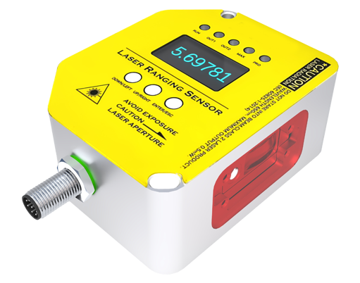
In the realm of industrial automation and electrical engineering, laser sensors are pivotal components for precision measurement, detection, and control. Understanding their schematic symbols and wiring diagrams is essential for accurate system design, installation, and troubleshooting. This guide provides a detailed breakdown of laser sensor symbols as per international standards, along with practical diagram interpretations.
Laser sensors operate by emitting a focused beam of light—typically from a laser diode—and detecting its reflection or interruption to gauge distance, presence, or position of objects. In electrical schematics, these sensors are represented using standardized symbols that convey their function without detailing internal mechanics. The core symbol for a laser emitter often resembles a circle with a diagonal arrow pointing outward, indicating light projection, while the receiver is depicted as a circle with a photodiode-like element. Combined units may show both within a single rectangular enclosure symbol, labeled "LAS" or with a specific model number.
According to IEC (International Electrotechnical Commission) and ANSI/IEEE standards, laser sensor symbols include annotations for electrical connections. For instance, a typical three-wire DC sensor symbol will have terminals marked: positive supply (V+ or brown wire), negative/ground (V- or blue wire), and output signal (black or white wire). The output type—whether NPN (sinking) or PNP (sourcing)—is indicated by the direction of an arrow on the output line. In diagrams, an NPN output symbol shows an arrow pointing toward the ground, meaning it sinks current to activate a load, while a PNP output arrow points away, sourcing current.
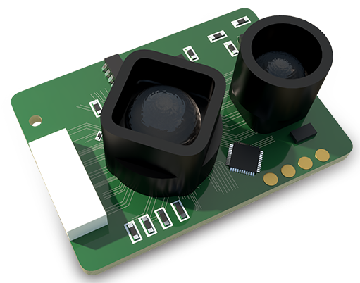
Wiring diagrams further illustrate how laser sensors integrate into control systems. A common setup involves connecting the sensor to a programmable logic controller (PLC) or relay. For example, in a retro-reflective laser sensor application, the diagram shows the emitter/receiver unit facing a reflector, with wiring to a PLC’s input module. The output wire from the sensor links to the PLC’s digital input, completing the circuit when the laser beam is broken. Diagrams often include protective elements like fuses or surge suppressors, denoted by standard fuse or varistor symbols, to safeguard against voltage spikes.

Another key aspect is the representation of adjustable parameters. Some laser sensor symbols incorporate small icons for sensitivity adjustment or timing functions, such as a potentiometer symbol or clock-like figure. These indicate user-configurable features for tuning detection thresholds. In complex diagrams, laser sensors may be part of a network using IO-Link or Ethernet/IP, symbolized by communication lines with protocol-specific annotations.
Practical interpretation requires attention to detail. For instance, a diffuse reflective laser sensor diagram might show a target object within the beam path, with dashed lines representing the sensing field. The symbol often includes a range indicator (e.g., "0.1-5m") nearby. Engineers must cross-reference these symbols with datasheets to ensure compatibility with power supplies (typically 10-30V DC) and load currents. Misinterpreting an NPN vs. PNP symbol can lead to incorrect PLC wiring, causing system failures.
In summary, mastering laser sensor symbols enhances efficiency in designing automated systems. Always refer to manufacturer documentation for model-specific variations, as symbols can differ slightly based on features like background suppression or analog outputs. By adhering to standard diagram conventions, engineers ensure reliable communication and operation across global projects.