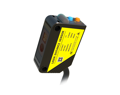
Profile laser sensors, also known as laser line scanners or triangulation sensors, are indispensable tools in modern industrial automation for non-contact, high-precision measurement of object dimensions, contours, and surface profiles. Their applications range from quality inspection and robot guidance to part positioning and assembly verification. However, achieving optimal performance hinges on meticulous calibration and systematic troubleshooting. This guide provides a detailed, step-by-step approach for engineers to effectively debug and fine-tune these sophisticated devices.
The initial and most critical phase is sensor installation and environmental preparation. Ensure the sensor is mounted securely on a vibration-free fixture, with its laser plane perpendicular to the intended measurement direction. The working distance must be within the sensor's specified range. Ambient lighting is a common source of interference; strong, direct light, especially from sources with similar wavelengths to the laser, can saturate the sensor's receiver. Employ physical barriers, hoods, or filters to mitigate this. The target surface's characteristics—color, reflectivity, texture, and material—significantly impact the laser line's visibility. Highly reflective or transparent surfaces may require applying a temporary matte coating, while dark, absorbent surfaces might need sensor sensitivity adjustment.
Calibration is the process of translating raw sensor data (pixels) into accurate, real-world dimensional units (e.g., millimeters). It establishes the relationship between the sensor's internal coordinate system and the physical world. The standard method involves scanning a certified calibration artifact, typically a precision gauge block or a target with known step heights. The sensor's accompanying software will guide you through this process: position the artifact within the field of view, capture its profile, and input the known dimensions. The software then calculates scaling factors and correction parameters. It is paramount to perform this calibration at the sensor's final operational temperature, as thermal drift can affect accuracy. For 3D applications involving multiple sensors or sensor motion, a spatial calibration (often using a sphere or checkerboard target) is necessary to unify all data into a single coordinate system.
Following calibration, parameter optimization within the sensor software is essential. Key parameters include:
* Exposure Time/Integration Time: Controls how long the camera chip collects light. Adjust to achieve a clear, bright laser line without blooming or saturation. Low exposure on dark surfaces results in a faint line; high exposure on shiny surfaces causes line broadening.
* Laser Power: Modulates the intensity of the projected laser line. Use the minimum power necessary for a stable signal to enhance laser diode lifespan and reduce ambient light effects.
* Threshold & Filtering: Set threshold levels to distinguish the laser line from background noise. Apply median or averaging filters to smooth profile data, but avoid over-filtering which can mask genuine surface features or reduce edge detection sharpness.
* Measurement ROI (Region of Interest): Define the specific area within the image where the laser line is analyzed. This excludes irrelevant background, drastically improving processing speed and reducing computational noise.
Even with careful setup, issues arise. A structured troubleshooting methodology is vital.
* Problem: No Laser Line or Incomplete Line Detection.
* Check: Power and communication cables (e.g., Ethernet, EtherCAT). Verify the laser safety interlock (if enabled).
* Solution: Ensure the laser is enabled in software. Inspect the lens for dirt or damage. Verify the object is within the measurement range and that the laser strikes the surface. Adjust exposure and threshold.
* Problem: Noisy, Unstable, or "Jumping" Profile Data.
* Check: Environmental vibrations, air turbulence (e.g., from cooling fans), or fluctuating ambient light.
* Solution: Improve mechanical stability. Shield the sensor from air currents and external light sources. Increase software filtering moderately and validate if the noise is consistent across multiple scans.
* Problem: Systematic Measurement Errors or Drift.
* Check: Calibration artifact accuracy and calibration procedure. Thermal conditions of the sensor and environment.
* Solution: Recalibrate using a verified standard. Allow the sensor to reach thermal equilibrium before critical measurements. Investigate if errors are linear (scaling issue) or non-linear (lens distortion, requiring recalibration).
* Problem: Poor Performance on Specific Surfaces.
* Check: Surface reflectivity and color.
* Solution: For glossy surfaces, tilt the sensor slightly off-perpendicular to avoid specular reflection directly back into the receiver. Utilize sensors with built-in automatic exposure control (AEC) or multiple exposure modes (HDR) for high-contrast scenes.
Regular maintenance ensures long-term reliability. Keep the protective window clean using appropriate lens cleaning materials. Periodically verify calibration, especially after physical shocks or significant environmental changes. Monitor the sensor's internal temperature and health status via software diagnostics if available.
In conclusion, successful debugging of a profile laser sensor is a systematic blend of mechanical precision, environmental control, precise calibration, and software parameter mastery. By understanding the core principles of optical triangulation and adhering to a methodical approach, engineers can unlock the full potential of these sensors, ensuring reliable, high-accuracy data for demanding industrial automation tasks. Always consult the specific manufacturer's manual for device-specific procedures and recommended settings.