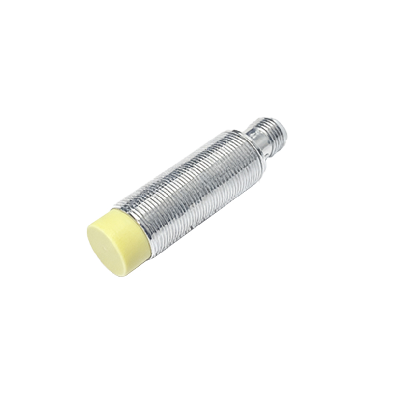
In industrial automation, proximity sensors play a critical role in detecting the presence or absence of objects without physical contact. These sensors are widely used for tasks such as counting, positioning, and safety monitoring. When integrating them with a simple Programmable Logic Controller (PLC), proper wiring and configuration are essential for reliable operation. This guide outlines the fundamental steps to connect proximity sensors to a basic PLC system, ensuring optimal performance in various applications.
First, identify the type of proximity sensor you are using. Common varieties include inductive sensors (for detecting metallic objects), capacitive sensors (for non-metallic materials), and photoelectric sensors (using light beams). Each type has specific wiring requirements, typically categorized as two-wire, three-wire, or four-wire sensors. For simplicity, we will focus on three-wire DC sensors, which are prevalent in industrial setups due to their ease of integration with PLCs.
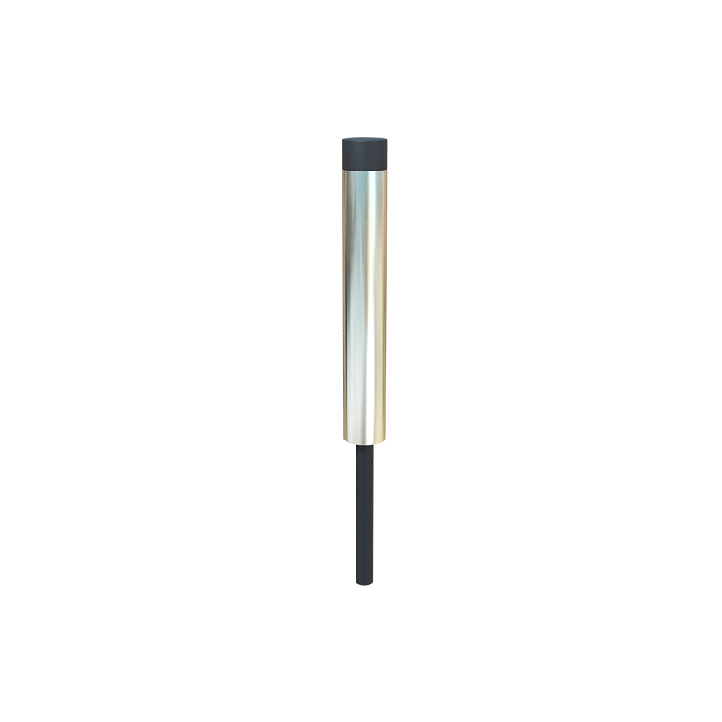
A three-wire proximity sensor generally includes three leads: brown (positive voltage), blue (negative or common), and black (signal output). Before proceeding, ensure the sensor’s voltage rating matches the PLC’s input module specifications—commonly 12-24V DC. Turn off all power sources to prevent electrical hazards during installation.
Start by connecting the sensor’s power supply. Attach the brown wire to the positive DC terminal (e.g., +24V) and the blue wire to the negative or ground terminal (0V). This provides the necessary operating voltage for the sensor. Next, link the sensor’s output (black wire) to one of the PLC’s digital input channels. Most simple PLCs have input modules with terminals labeled for each channel; refer to the PLC manual for exact pin assignments.
If the sensor is NPN-type (sinking output), the black wire will connect to the PLC input, and the input’s common terminal should be tied to positive voltage. For PNP-type (sourcing output), the black wire connects to the PLC input, with the input common linked to ground. Verify your sensor’s output type, as incorrect wiring can lead to malfunction or damage. Once wired, secure connections with appropriate terminals or connectors to avoid loose contacts.
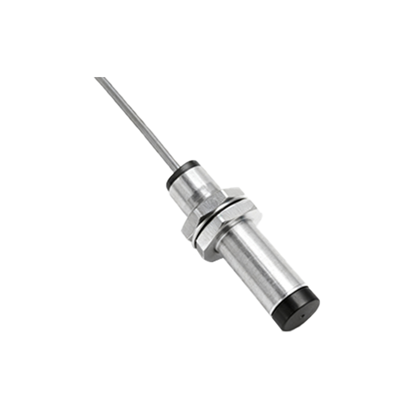
After wiring, power up the system and test the sensor. Place a target object within the sensor’s detection range. The sensor’s indicator light should activate, and the corresponding PLC input LED should illuminate, confirming signal reception. Use the PLC programming software (e.g., ladder logic) to monitor the input status. For instance, assign the input address (e.g., I0.0) to a contact in the ladder diagram to trigger outputs like relays or indicators.
In programming, consider factors like response time and debouncing. Proximity sensors can generate noise or rapid signal changes; adding a timer or filter in the PLC program ensures stable operation. For example, use a delay function to ignore brief fluctuations, enhancing accuracy in counting applications. Additionally, configure fail-safe measures, such as alarm routines for sensor faults, to maintain system integrity.
Finally, document the setup, including wiring diagrams and program notes, for future maintenance. Regular checks on sensor alignment and cleanliness prevent false triggers. By following these steps, you can effectively integrate proximity sensors with a simple PLC, enabling efficient automation in environments like packaging, assembly lines, or material handling. Always adhere to safety standards and manufacturer guidelines to ensure long-term reliability.