Proximity level sensors are widely used in industrial automation for detecting the presence or absence of liquids, solids, or granular materials without physical contact. These sensors operate based on electromagnetic, capacitive, or ultrasonic principles, with each type having distinct schematic configurations tailored to specific applications. Understanding the schematic design is crucial for proper installation, troubleshooting, and optimization in electrical engineering projects.
A typical inductive proximity sensor schematic for liquid level detection includes an oscillator circuit, a demodulator, and an output switching stage. The oscillator generates a high-frequency electromagnetic field at the sensing face. When a conductive target (such as a metal tank wall or liquid) enters this field, eddy currents are induced, causing a change in the oscillator's amplitude. This change is detected by the demodulator, which then triggers the output circuit—usually a solid-state switch or relay—to change state. The schematic often incorporates protection components like reverse polarity diodes, transient voltage suppressors, and filtering capacitors to ensure reliability in harsh industrial environments.
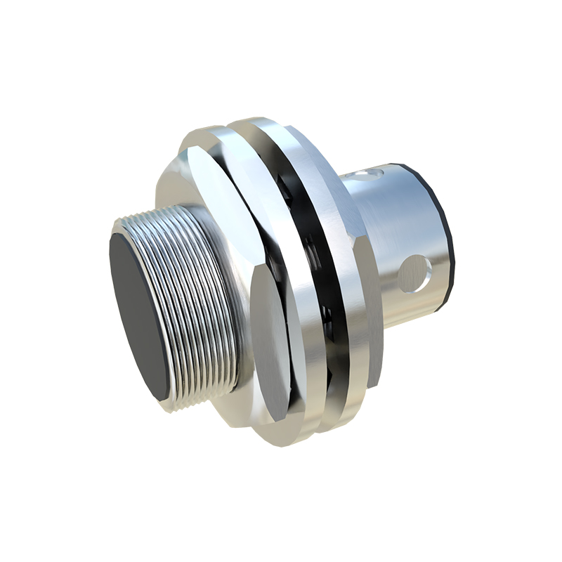
Capacitive proximity sensors, suitable for both conductive and non-conductive materials, feature a different schematic approach. The core circuit consists of a capacitive plate acting as one electrode of a capacitor, with the target material acting as the other. An internal oscillator is tuned so that the capacitance change alters the oscillation amplitude when the target approaches. This variation is processed by a threshold detector, which activates the output. Key components in the schematic include sensitivity adjustment potentiometers, shielding to reduce false triggers, and RC networks for noise immunity. These sensors are ideal for detecting liquids through non-metallic containers, as the schematic allows tuning to ignore the container wall.
Ultrasonic proximity sensors employ a more complex schematic involving piezoelectric transducers, timing circuits, and signal processors. The transmitter emits high-frequency sound waves, which reflect off the liquid surface and return to the receiver. The schematic includes a microcontroller or dedicated IC to calculate the time-of-flight, converting it into a distance or level measurement. Critical parts in the schematic are the driver circuit for the transducer, amplifiers for the echo signal, and temperature compensation modules to account for air density changes. These sensors excel in applications requiring continuous level monitoring, with schematics emphasizing accuracy and stability.
When analyzing any proximity level sensor schematic, engineers must consider power supply requirements (typically 10-30V DC or 90-250V AC), output types (PNP/NPN, analog, or IO-Link), and environmental factors like temperature ranges or hazardous area certifications. Proper interpretation of the schematic symbols—such as IEC standards for switches, transistors, and integrated circuits—ensures correct integration into control systems like PLCs or DCS. Additionally, modern schematics may include diagnostic LEDs, short-circuit protection, and programmable logic for smart sensor functionalities.
In practice, schematic variations exist based on manufacturer designs, but the fundamental principles remain consistent. For instance, two-wire AC/DC sensors simplify wiring by combining power and output in one loop, while three-wire designs separate supply and output for better performance. Engineers should always refer to the specific schematic provided in the sensor datasheet, paying attention to wiring diagrams, load connections, and grounding recommendations to prevent issues like electromagnetic interference or false triggering.
Ultimately, mastering proximity level sensor schematics empowers electrical professionals to select the right sensor type, configure it accurately, and maintain system integrity. Whether for tank level control in chemical plants, bin monitoring in food processing, or leak detection in water management, a deep schematic understanding enhances efficiency and safety across industries.