Proximity sensors are indispensable components in modern industrial automation, providing non-contact detection of objects. Their ability to operate reliably in harsh environments without physical wear makes them superior to mechanical limit switches. This article delves into the fundamental circuits of the most common types: inductive, capacitive, and photoelectric proximity sensors, explaining their design principles, typical operating parameters, and key considerations for implementation.
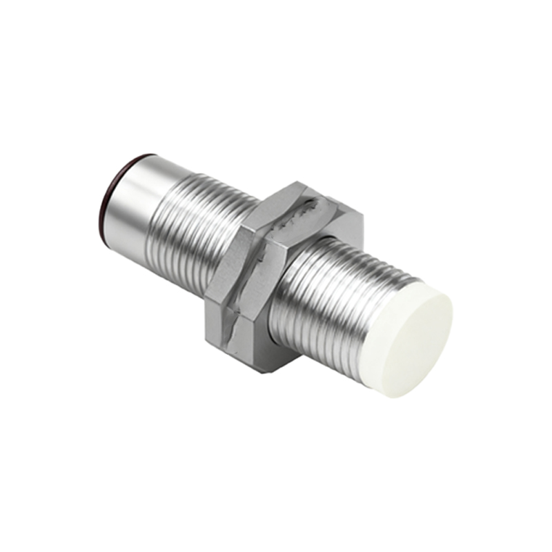
Inductive proximity sensors are the workhorses for detecting metallic objects. Their core circuit revolves around a high-frequency oscillator coil, a detection circuit, and an output stage. The oscillator generates a high-frequency electromagnetic field from the sensing face. When a ferrous or non-ferrous metal object enters this field, eddy currents are induced on the object's surface. This causes a measurable energy loss (damping) in the oscillator circuit. The detection circuit, often a Schmitt trigger, monitors the oscillator's amplitude. Once the damping exceeds a predefined threshold, it triggers a signal change. The output stage then switches a solid-state transistor (PNP or NPN sourcing/sinking) or, in some older models, a relay. Key design considerations include the sensing distance (typically a fraction of the sensor's nominal range for reliability), the target material's influence (steel offers the longest range, while aluminum and copper have reduced factors), and immunity to electrical noise, which is achieved through shielded designs and proper grounding. Standard output configurations include 3-wire DC (the most common), 2-wire AC/DC, and analog (4-20 mA or 0-10V) variants for distance-proportional measurement.
Capacitive proximity sensors share a similar circuit topology but are designed to detect a wider range of materials, including metals, plastics, liquids, and granular substances. The circuit forms a capacitor between the sensor's active face (one plate) and the target (the other plate), with the air gap as the dielectric. An internal oscillator's frequency is affected by the change in capacitance when any material with a sufficient dielectric constant enters the sensing zone. The detection circuit interprets this frequency shift. A major circuit challenge is compensating for background or parasitic capacitance, which is addressed with a sensitivity adjustment potentiometer. This allows the user to tune out the influence of the mounting bracket or a container wall, focusing sensitivity on the target material. These sensors are crucial in level detection for non-metallic tanks, material handling, and presence detection of packaged goods. Their circuits must be carefully calibrated to avoid false triggers from humidity or dust accumulation.
Photoelectric sensors, while also proximity devices, operate on an entirely different optical principle. Their circuits are more complex, integrating a light emitter (usually an LED in infrared, red, or laser wavelengths), a receiver (phototransistor or photodiode), and sophisticated signal processing. There are three primary modes with distinct circuit requirements. The through-beam (opposed) mode uses separate emitter and receiver units; the circuit is relatively simple, checking for the presence or absence of the light beam. The retro-reflective mode uses a single housing with both emitter and receiver, relying on a reflector; its circuit must filter out the reflected signal from the target's reflection, often using polarization filters. The most versatile and common is the diffuse (proximity) mode, where the sensor detects light reflected directly from the target. Its circuit faces the challenge of detecting a weak, variable return signal. To achieve this, it often employs modulated (pulsed) LED light and synchronous detection circuitry. This technique allows the receiver to amplify only the signal synchronized with the emitter's pulse frequency, effectively rejecting ambient light from factory lighting. Advanced versions include background suppression and foreground suppression sensors, which use triangulation principles with multiple receiver elements to define a precise sensing window.
Regardless of type, all proximity sensor circuits require careful integration into a control system. Key interfacing considerations include: ensuring correct polarity for DC sensors; using flyback diodes or RC networks to protect transistor outputs from voltage spikes when driving inductive loads like relays or solenoids; providing adequate derating for current and voltage; and implementing proper wiring practices—keeping sensor cables away from power lines to prevent electromagnetic interference. For analog sensors, signal conditioning and scaling circuits are necessary to convert the current or voltage signal into a usable value for a Programmable Logic Controller (PLC) or process controller.
In conclusion, the reliability of an automated system hinges on selecting the correct proximity sensor and understanding its underlying circuitry. Inductive sensors offer rugged metal detection, capacitive sensors provide material versatility, and photoelectric sensors deliver long-range and precise optical sensing. By matching the sensor's circuit characteristics—such as output type, sensing principle, and environmental immunity—to the specific application requirements, engineers can build robust, maintenance-free detection systems that form the sensory foundation of Industry 4.0.