In industrial automation and electrical systems, proximity sensors play a critical role in detecting the presence or absence of objects without physical contact. The V10 series proximity sensor, known for its durability and precision, is widely used in machinery, conveyor systems, and safety applications. However, like all components, it may require replacement due to wear, damage, or performance degradation. This guide provides a step-by-step process for replacing a V10 proximity sensor, ensuring minimal downtime and optimal functionality.
Before initiating the replacement, conduct a thorough assessment. Verify the sensor model (e.g., V10-AN-2M) and specifications, such as sensing range, output type (PNP or NPN), and voltage rating (typically 10-30V DC). Ensure the system is powered off and locked out following standard safety protocols—use lockout/tagout (LOTO) procedures to prevent accidental energization. Gather necessary tools: a multimeter, screwdrivers, wire strippers, and a replacement V10 sensor with matching parameters.
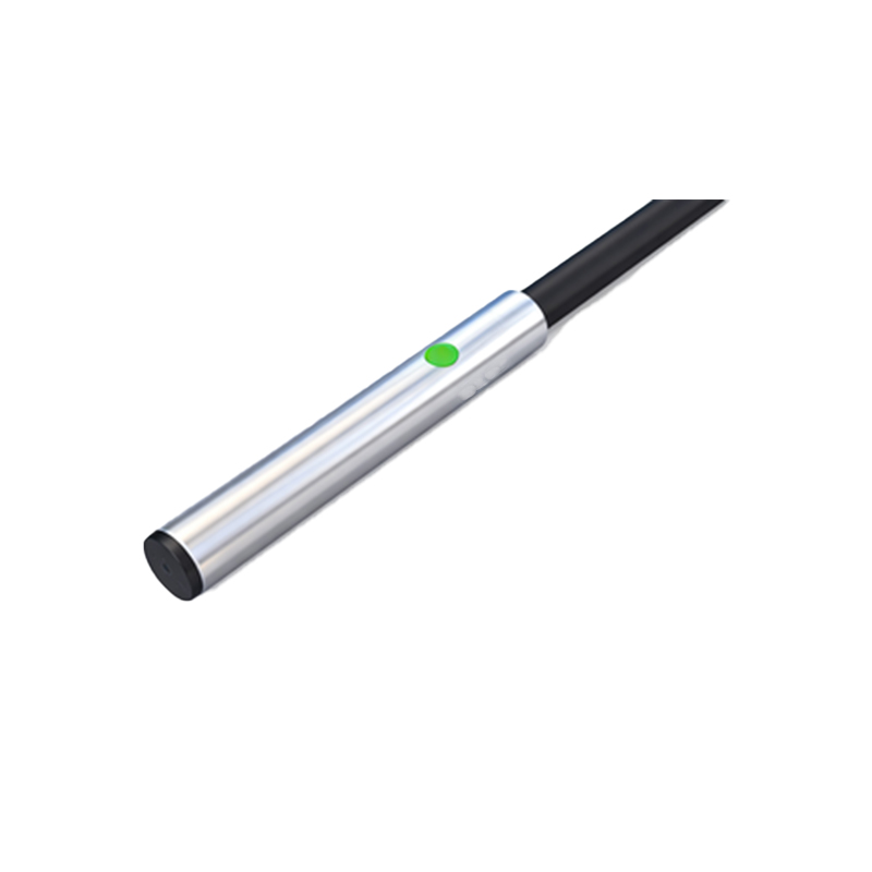
Start by disconnecting the electrical connections. The V10 sensor usually features a quick-disconnect cable or terminal block. Label each wire according to the wiring diagram (common labels: brown for +V, blue for ground, black for output). Use the multimeter to confirm no residual voltage exists. Remove the sensor from its mounting bracket—typically secured with nuts or bolts. Note the orientation and sensing distance, as improper alignment can affect performance.
Install the new V10 sensor by reversing the removal steps. Mount it securely in the same position, ensuring the sensing face is unobstructed and aligned with the target object. Reconnect the wires precisely as labeled, double-checking connections against the manufacturer’s datasheet. For enhanced reliability, apply dielectric grease to terminals to prevent corrosion. Once installed, power on the system gradually. Test the sensor by introducing a target object within its sensing range; use the multimeter to verify output signal accuracy (e.g., voltage switch from 0V to supply voltage).
Troubleshooting common issues post-replacement is essential. If the sensor fails to detect, check wiring polarity and power supply. Ensure the sensing distance matches the application—adjust if necessary using the potentiometer on some V10 models. Environmental factors like dust, moisture, or electromagnetic interference can impact performance; consider installing protective housings or shields. Document the replacement in maintenance logs, including date, sensor serial number, and test results, to aid future diagnostics.
Regular maintenance extends sensor life. Clean the sensing surface periodically, inspect for physical damage, and monitor output consistency. The V10 sensor’s robust design suits harsh industrial environments, but proactive checks prevent unexpected failures. By following this guide, electrical engineers can ensure efficient V10 proximity sensor replacements, maintaining system integrity and safety.