Infrared proximity sensors are widely used in industrial automation, robotics, and safety systems for non-contact detection of objects. Understanding the correct wiring is crucial for ensuring reliable operation and preventing damage to the sensor or connected equipment. This guide provides a detailed overview of infrared proximity sensor wiring, supported by clear diagrams and practical tips.
Most infrared proximity sensors consist of three main terminals: VCC (power supply), GND (ground), and OUT (signal output). The VCC terminal typically requires a DC voltage, commonly 5V, 12V, or 24V, depending on the sensor model. It is essential to verify the voltage rating specified in the datasheet to avoid overvoltage. The GND terminal must be connected to the common ground of the power supply and control system, ensuring a stable reference point. The OUT terminal provides a digital or analog signal indicating the presence or absence of an object within the detection range. For digital sensors, the output is often an NPN or PNP transistor switch, while analog sensors output a voltage proportional to distance.
A standard wiring diagram for an NPN-type infrared proximity sensor shows the VCC connected to the positive rail of the power supply, GND to the negative rail, and the OUT terminal to the input of a PLC, microcontroller, or relay. In this configuration, the sensor acts as a sinking device, meaning it switches the ground connection to the load. For PNP-type sensors, the OUT terminal switches the positive voltage to the load. It is critical to match the sensor output type with the input requirements of the receiving device. Incorrect pairing can lead to malfunction or permanent damage.
When wiring multiple sensors, use a regulated power supply with adequate current capacity to prevent voltage drops. Each sensor should be connected in parallel to the power source, with separate cables for the output signals to avoid interference. Shielded cables are recommended for long-distance wiring or in electrically noisy environments to minimize false triggers. Additionally, always install fuses or circuit breakers in the power line to protect against short circuits.
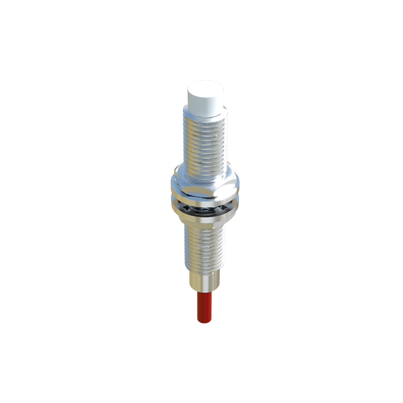
For analog infrared sensors, the wiring is similar, but the OUT terminal connects to an analog input module. The output signal, usually 0-10V or 4-20mA, must be calibrated according to the sensor's range. Ensure the receiving device's analog input is configured to match the signal type and scale. Ground loops can cause signal inaccuracies, so use a single-point grounding scheme and avoid running signal cables parallel to high-voltage lines.
Testing the wiring involves applying power and observing the sensor's indicator LED, which typically lights up when an object is detected. Use a multimeter to check voltage levels at each terminal. For digital sensors, verify the output switches between high and low states as an object moves in and out of range. For analog sensors, measure the output voltage or current at various distances to confirm linearity.
Common wiring mistakes include reversed polarity, incorrect voltage, loose connections, and improper grounding. These errors can lead to erratic behavior, reduced sensitivity, or sensor failure. Always refer to the manufacturer's wiring diagram and follow industry standards for electrical installations. Regular maintenance, such as cleaning the sensor lens and checking cable integrity, ensures long-term performance.
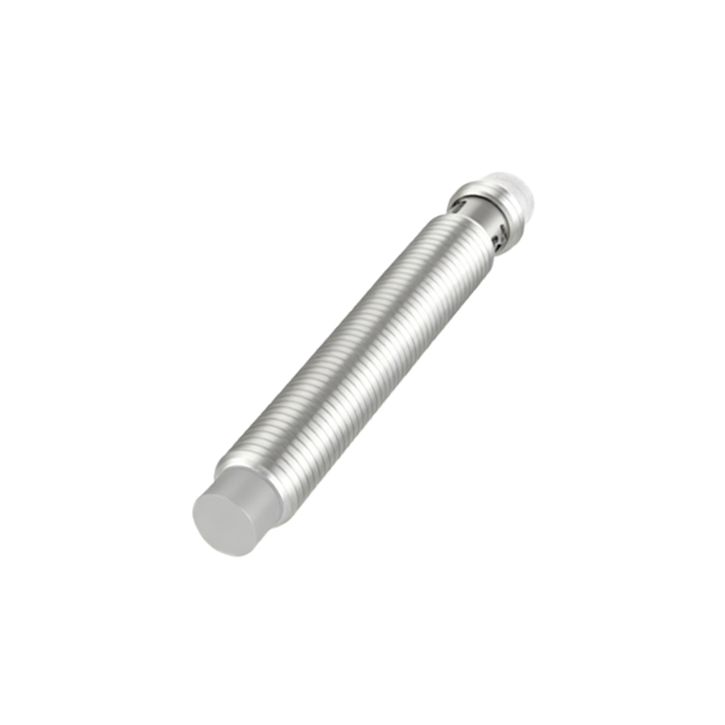
In summary, proper wiring of infrared proximity sensors is fundamental to system reliability. By adhering to the diagrams and guidelines provided, engineers can achieve accurate detection and seamless integration into automated systems. For complex setups, consult technical documentation or seek assistance from certified professionals.