In industrial automation, proximity switch sensors play a critical role in ensuring the safe and efficient operation of grinding machines. These non-contact sensors detect the presence or absence of metallic objects, enabling precise control over machine functions such as positioning, speed regulation, and safety interlocks. Proper wiring is essential to maximize sensor performance, prevent equipment damage, and ensure operator safety. This guide provides a step-by-step overview of wiring proximity switch sensors for grinding machines, adhering to industry standards and best practices.
First, identify the type of proximity sensor installed in your grinding machine. Common variants include inductive sensors (for detecting ferrous metals) and capacitive sensors (for non-metallic materials). Most grinding machines use inductive sensors due to their reliability in metal-rich environments. Check the sensor specifications, typically labeled on the housing, to determine its operating voltage (e.g., 10-30V DC or 90-250V AC), output type (e.g., NPN or PNP for DC sensors, NO/NC contacts), and sensing range. Always refer to the manufacturer’s datasheet for precise details.
Before starting any wiring work, ensure the grinding machine is completely powered off and locked out following safety protocols (e.g., LOTO—Lock Out, Tag Out). Verify that all electrical sources are disconnected to prevent accidental shocks or short circuits. Gather necessary tools, such as insulated screwdrivers, wire strippers, multimeter, and appropriate cables rated for industrial environments (e.g., shielded cables to reduce electromagnetic interference).
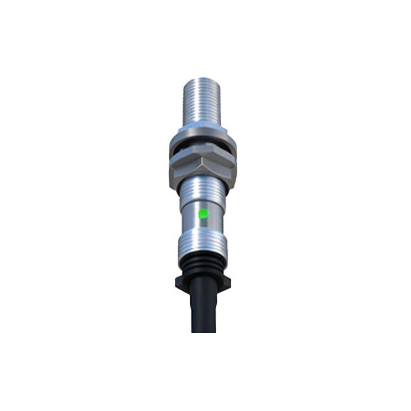
Wiring steps vary based on the sensor’s output configuration. For DC sensors (common in modern grinding machines):
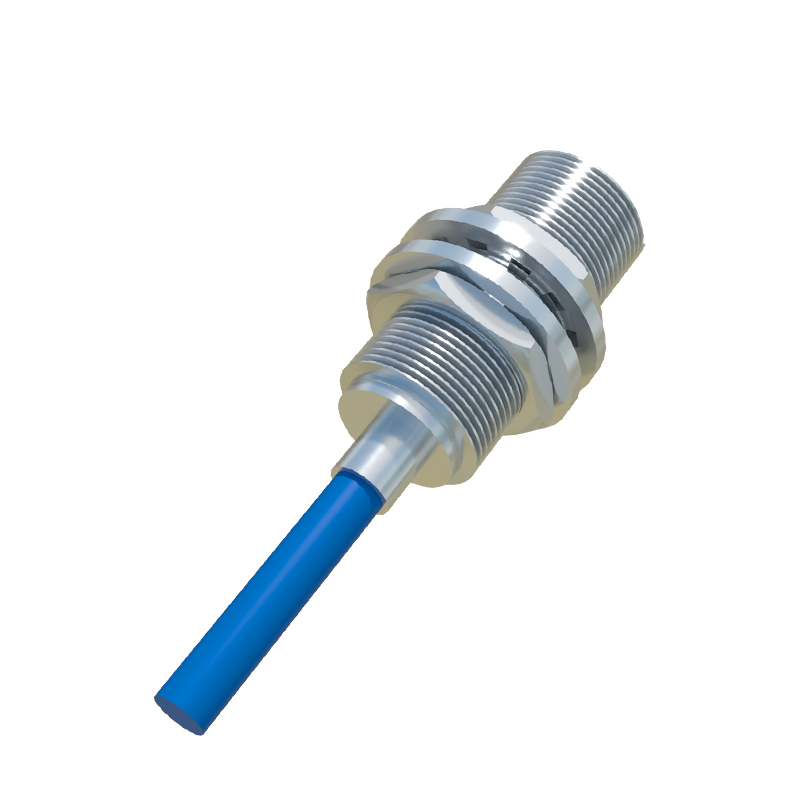
- NPN Sensors (Sinking Output): Connect the brown wire (typically positive) to the DC power supply’s positive terminal (+V). Attach the blue wire (negative) to the power supply’s common ground (0V). The black wire is the output signal; link it to the PLC (Programmable Logic Controller) or relay input. When the sensor detects an object, it switches the output to ground, completing the circuit.
- PNP Sensors (Sourcing Output): Wire the brown wire to +V and the blue wire to ground. The black output wire connects to the PLC/relay, providing a positive voltage signal upon detection.
For AC sensors (less common but used in high-power setups), connect the brown wire to the phase line (L) and the blue wire to the neutral (N). The black output wire interfaces with the control system.
Always use conduit or cable trays to protect wires from abrasion, heat, or coolant exposure in grinding environments. Maintain proper cable lengths—excessive length can cause signal attenuation. For sensors with built-in LED indicators, verify operation by testing with a metal object; the LED should illuminate upon detection. Use a multimeter to check voltage continuity and ensure no loose connections exist.
Integrate the sensor into the grinding machine’s control loop by connecting its output to the PLC’s digital input module or a safety relay. Configure the PLC program to interpret sensor signals for tasks like triggering emergency stops, monitoring wheel wear, or automating feed cycles. For multiple sensors, label each wire clearly to simplify troubleshooting. Ground all shields to minimize noise interference, which is crucial in high-vibration grinding applications.
Regular maintenance is key to long-term reliability. Inspect wiring periodically for signs of wear, corrosion, or damage from metal dust or coolants. Test sensor alignment and sensing range annually, as misalignment can lead to false triggers or failures. Replace sensors if response times degrade or physical damage occurs.
By following these guidelines, engineers can ensure robust and safe wiring for proximity switch sensors in grinding machines. Always prioritize manufacturer instructions and local electrical codes to adapt to specific machine models or operational requirements.