Laser sensors have become indispensable components in modern industrial automation, offering unparalleled precision, speed, and reliability. Their operation is fundamentally based on the principles of optical triangulation, time-of-flight (ToF), or laser Doppler vibrometry, each suited to specific measurement tasks. Understanding common laser sensor schematics is crucial for engineers to select, integrate, and troubleshoot these devices effectively. This article details several typical laser sensor configurations and their practical applications.
One of the most prevalent schematics is the Optical Triangulation Sensor. This design typically consists of a laser diode, a focusing lens, a position-sensitive detector (PSD) or a CMOS/CCD array, and signal processing circuitry. The laser diode emits a focused beam onto the target surface. The reflected light is captured by the receiver lens at an angle and projected onto the PSD. The position of the light spot on the detector shifts proportionally to the distance of the target. This displacement is converted into an electrical signal, processed, and output as a precise distance or displacement value. These sensors excel in high-resolution, short-to-medium range applications such as wafer thickness measurement, surface profiling, and part presence detection on assembly lines. Their schematic highlights the critical alignment between the emitter, receiver, and the target plane.
For longer-range distance measurement and level sensing, the Time-of-Flight (ToF) Laser Sensor schematic is dominant. Its core components include a pulsed laser emitter (often a VCSEL), a high-speed photodetector (like an APD or SPAD), and precise timing circuitry. The sensor calculates distance by measuring the time delay between the emission of a laser pulse and the detection of its reflection. The formula *d = (c * Δt)/2*, where *c* is the speed of light, is fundamental. The schematic emphasizes the need for ultra-fast electronic components to achieve millimeter accuracy over distances of several meters to hundreds of meters. Common applications include bulk material level monitoring in silos, vehicle detection for automated guided vehicles (AGVs), and obstacle avoidance in robotics. The robustness of ToF sensors against varying surface colors and textures is a key advantage derived from their pulsed operation.
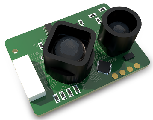
In contrast, the Laser Confocal Displacement Sensor employs a more complex optical schematic. It uses a white light source or a multi-wavelength laser, a confocal pinhole, and a spectrometer. Only light reflected from the exact focal point passes through the pinhole to the spectrometer, which analyzes the wavelength. As the target distance changes, the wavelength of the focused light shifts. By detecting this spectral shift, the sensor determines displacement with nanometer-level accuracy. This schematic is central to applications demanding extreme precision, such as measuring transparent film thickness, inspecting micro-electromechanical systems (MEMS), or profiling high-gloss surfaces where standard triangulation fails due to specular reflection.
Another critical schematic is for Laser Micrometer and Gap Sensors. These often use two parallel laser scan lines or a single beam scanned across a target. The receiver opposite the emitter detects the shadow or the reflected beam profile. The schematic focuses on the synchronized scanning mechanism and the receiver's ability to capture the exact edges of the target's shadow. The time difference between beam obstruction at the edges is used to calculate dimensions like diameter, width, or gap size with micron resolution. They are vital in rolling mills for wire diameter control, and in automotive manufacturing for verifying component clearances.
For vibration and velocity analysis, the Laser Doppler Vibrometer (LDV) schematic is essential. It is based on the interference of a reference laser beam and a beam reflected from a vibrating surface. The Doppler shift in the frequency of the reflected light, proportional to the target's velocity, is detected using an interferometer. The schematic details the beam splitter, the reference arm, and the photodetector that converts the optical interference pattern into a velocity signal. This non-contact measurement is indispensable for predictive maintenance, analyzing motor or turbine blade vibrations, and in acoustic research.
Integration of these sensors into a control system involves understanding their output schematics: analog (4-20 mA, 0-10 V), digital (RS-485, IO-Link), or fieldbus protocols (PROFIBUS, EtherCAT). The wiring diagram must account for power supply, output signals, and often teach-in or configuration interfaces. Proper shielding and grounding are paramount in the electrical schematic to mitigate electromagnetic interference in noisy industrial environments.
In summary, the schematic of a laser sensor dictates its capability. From the straightforward triangulation design for proximity tasks to the sophisticated confocal and Doppler setups for ultra-precise metrology, each schematic solves a distinct set of industrial challenges. Mastery of these diagrams enables engineers to harness the full potential of laser sensing technology, driving advancements in automation quality control and process optimization. Future trends point towards miniaturization of these schematics and the integration of AI directly at the sensor node for smarter, edge-based decision-making.