In industrial automation and control systems, proximity switch sensors are indispensable components for detecting the presence or absence of objects without physical contact. A critical aspect of their performance and integration is understanding their current specifications, which directly impact reliability, safety, and system compatibility. This article delves into the key current-related parameters, their significance, and practical considerations for engineers.
Proximity sensors typically operate on direct current (DC) or alternating current (AC) power supplies, with DC versions being more common in modern applications due to their stability and ease of interfacing with programmable logic controllers (PLCs). The current specifications primarily include load current, leakage current, inrush current, and residual current, each playing a distinct role in sensor functionality.
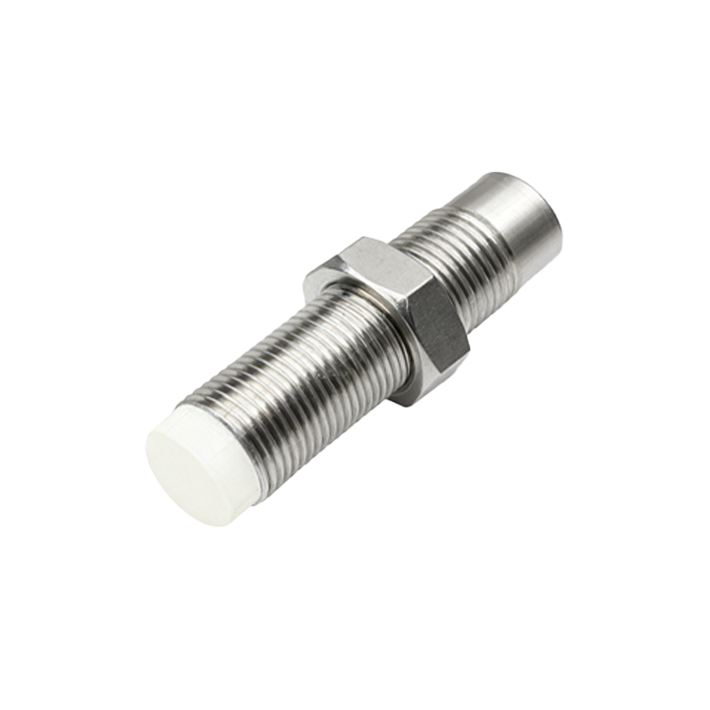
Load current, often referred to as the switching current, is the maximum current the sensor can handle when its output is active. For example, a standard DC proximity sensor might have a load current rating of 200 mA, meaning it can safely control devices like relays or solenoids within this limit. Exceeding this value can lead to overheating, reduced lifespan, or failure. Engineers must ensure that the connected load does not surpass the sensor's rated load current, considering factors like inductive loads that may cause voltage spikes.
Leakage current is a small current that flows even when the sensor is in the off state, typically in the range of microamperes to a few milliamperes. While minimal, it can cause issues in sensitive circuits, such as falsely triggering PLC inputs or keeping LEDs dimly lit. To mitigate this, using a bleeder resistor or selecting sensors with low leakage current (e.g., below 1 mA) is advisable, especially in high-precision applications.
Inrush current occurs momentarily when the sensor is powered on, often higher than the steady-state current due to capacitive charging in the internal circuitry. This surge can stress power supplies and cause nuisance tripping of circuit breakers. Manufacturers specify inrush current limits, and engineers should account for this by designing power circuits with adequate headroom or using soft-start mechanisms to limit peak currents.
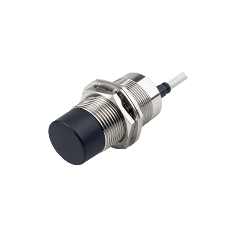
Residual current relates to sensors in AC applications, where a small current may persist after switching off due to capacitive effects. This can be hazardous in safety-critical systems, requiring careful selection of sensors with minimal residual current or additional isolation measures.
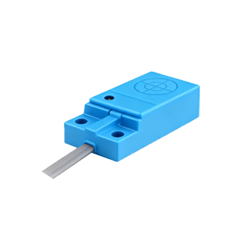
Current consumption, or the sensor's own operating current, is another vital parameter. Lower current consumption enhances energy efficiency and reduces heat generation, which is crucial in densely packed control panels. For instance, a sensor drawing 15 mA at 24 VDC is more efficient than one drawing 25 mA, contributing to lower overall system power demands.
When integrating proximity sensors, engineers must also consider the current sinking vs. sourcing configurations. In sinking (NPN) sensors, current flows from the load to the sensor, common in Asian and European designs, while sourcing (PNP) sensors supply current to the load, prevalent in North America. Mismatching these with PLC inputs can lead to malfunction, so verifying compatibility is essential.
Environmental factors like temperature affect current ratings. High ambient temperatures can derate the sensor's current capacity, necessitating derating curves provided in datasheets. For example, a sensor rated for 300 mA at 25°C might only handle 250 mA at 60°C. Ignoring this can compromise performance in harsh industrial settings.
In practice, selecting the right proximity sensor involves balancing current specifications with application needs. For high-speed counting tasks, sensors with fast response times and low leakage current are preferred to avoid false signals. In heavy-duty machinery, robust sensors with high load current ratings and protection against overloads are critical. Always refer to manufacturer datasheets and adhere to standards like IEC 60947-5-2 for guidance.
Testing current parameters during installation using multimeters or oscilloscopes helps validate performance. Regular maintenance, including checking for current drift or abnormal leakage, ensures long-term reliability. As technology advances, sensors with integrated diagnostics and current monitoring features are becoming available, simplifying troubleshooting and enhancing system intelligence.
In summary, current specifications in proximity switch sensors are not mere technical details but foundational to system integrity. By thoroughly understanding and applying these parameters, engineers can optimize sensor selection, prevent operational issues, and build resilient automation systems that meet the demands of modern industry.