In the realm of industrial automation and precision measurement, laser position sensors have become indispensable tools. Their ability to provide non-contact, high-accuracy measurements of displacement, vibration, and thickness is critical for quality control, robotics, and process monitoring. A fundamental yet often nuanced specification that dictates their performance in dynamic applications is frequency response. This article delves into the technical aspects of frequency in laser position sensors, explaining its importance, influencing factors, and practical implications for system design.
At its core, the frequency response of a sensor describes how its output signal behaves when the target's position changes at varying speeds or frequencies. It is typically characterized by a bandwidth specification, often denoted in Hertz (Hz). A bandwidth of 1 kHz, for example, means the sensor can accurately track position changes that occur at rates up to 1,000 times per second. Beyond this cutoff frequency, the sensor's output will begin to attenuate or lag, introducing measurement errors. For static or slowly moving targets, this is less critical. However, for applications involving high-speed machinery, vibrating components, or fast-moving production lines, a sensor with insufficient bandwidth will fail to capture the true motion profile, leading to flawed data and potential process failures.
Several key factors determine the frequency capability of a laser position sensor. Firstly, the underlying measurement principle plays a role. Triangulation-based sensors, common for medium-range applications, involve imaging a laser spot onto a detector array. The processing speed of this detector and associated circuitry sets a limit on sampling rate. Conversely, confocal chromatic or interferometric sensors, used for ultra-high precision, may have different bandwidth constraints based on optical and signal processing complexities. Secondly, the internal sampling rate and signal processing algorithms are paramount. A sensor might sample data at 50 kHz internally but use digital filtering to output a cleaner, lower-noise signal at a lower effective bandwidth. Engineers must distinguish between internal sampling rate and usable analog or digital output bandwidth.
The type of output interface also influences practical frequency performance. Analog outputs (e.g., 0-10V, 4-20mA) have inherent bandwidth limitations defined by their circuitry and can be susceptible to noise in electrically noisy industrial environments. Digital outputs (e.g., RS-422, Ethernet-based protocols like EtherCAT) can transmit data at very high rates, but the effective update rate to the controller is determined by the sensor's processing cycle and the network protocol's cycle time. A sensor with a 10 kHz measurement capability but a 1 ms EtherCAT cycle time effectively provides data at 1 kHz to the PLC.
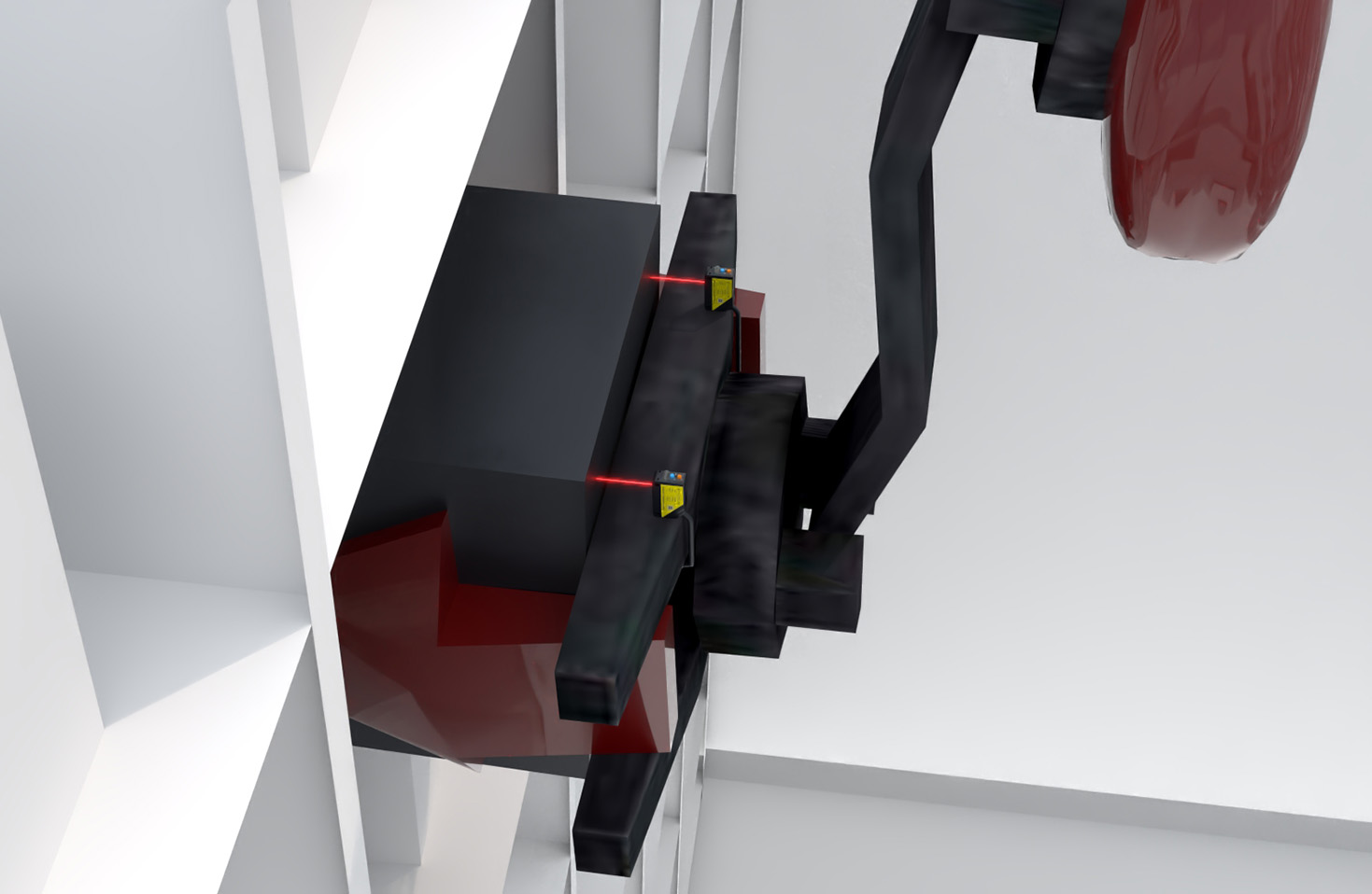
In application, selecting the appropriate frequency response requires careful analysis. Consider measuring the vibration of a motor shaft. The vibration spectrum may contain components from 10 Hz to 2000 Hz. To accurately characterize it, the sensor's bandwidth must exceed 2000 Hz, following the Nyquist-Shannon sampling theorem, which suggests a sampling rate at least twice the highest frequency of interest. Furthermore, the sensor's response should be flat (minimal gain variation) and have a linear phase shift within the bandwidth to avoid distorting the signal waveform. Resonant frequencies in the sensor's mechanical housing or the target's structure must also be considered, as they can cause amplified oscillations that corrupt measurements.

System integration introduces additional considerations. Long cables for analog signals can act as low-pass filters, reducing effective bandwidth. Electrical noise from drives and motors can superimpose high-frequency noise on the signal. Therefore, proper shielding, grounding, and sometimes external signal conditioners are necessary to preserve the sensor's native frequency performance. For ultra-high-speed applications, such as monitoring the flutter of a turbine blade, specialized high-bandwidth sensors with MHz-range capabilities are employed, though often at a higher cost and with more stringent installation requirements.
Ultimately, understanding frequency response is not merely about reading a datasheet specification. It involves a holistic view of the measurement chain: the target's dynamics, the sensor's inherent capabilities, the output path, and the data acquisition system. Over-specifying bandwidth can lead to unnecessary cost and increased susceptibility to high-frequency noise. Under-specifying it guarantees inaccurate measurements. By rigorously defining the required measurement speed and dynamic characteristics of the target motion, engineers can select a laser position sensor with the optimal frequency response, ensuring reliable, high-fidelity data that drives efficiency and quality in modern industrial systems.