Connecting a laser sensor correctly is crucial for ensuring accurate measurements, system reliability, and operational safety in industrial applications. As an experienced electrical engineer, I will guide you through the essential steps, considerations, and best practices for integrating a laser sensor into your control system. This guide assumes a basic understanding of electrical circuits and sensor terminology.
First, identify the type of laser sensor you are using. Common variants include diffuse reflective, through-beam, and retro-reflective sensors, each with specific wiring requirements. Typically, laser sensors operate on DC voltages (e.g., 10-30 VDC) or sometimes AC, so always verify the supply specifications on the sensor datasheet. Most industrial laser sensors have three or four wires: brown (positive), blue (negative), black (output), and sometimes white (second output or control line).
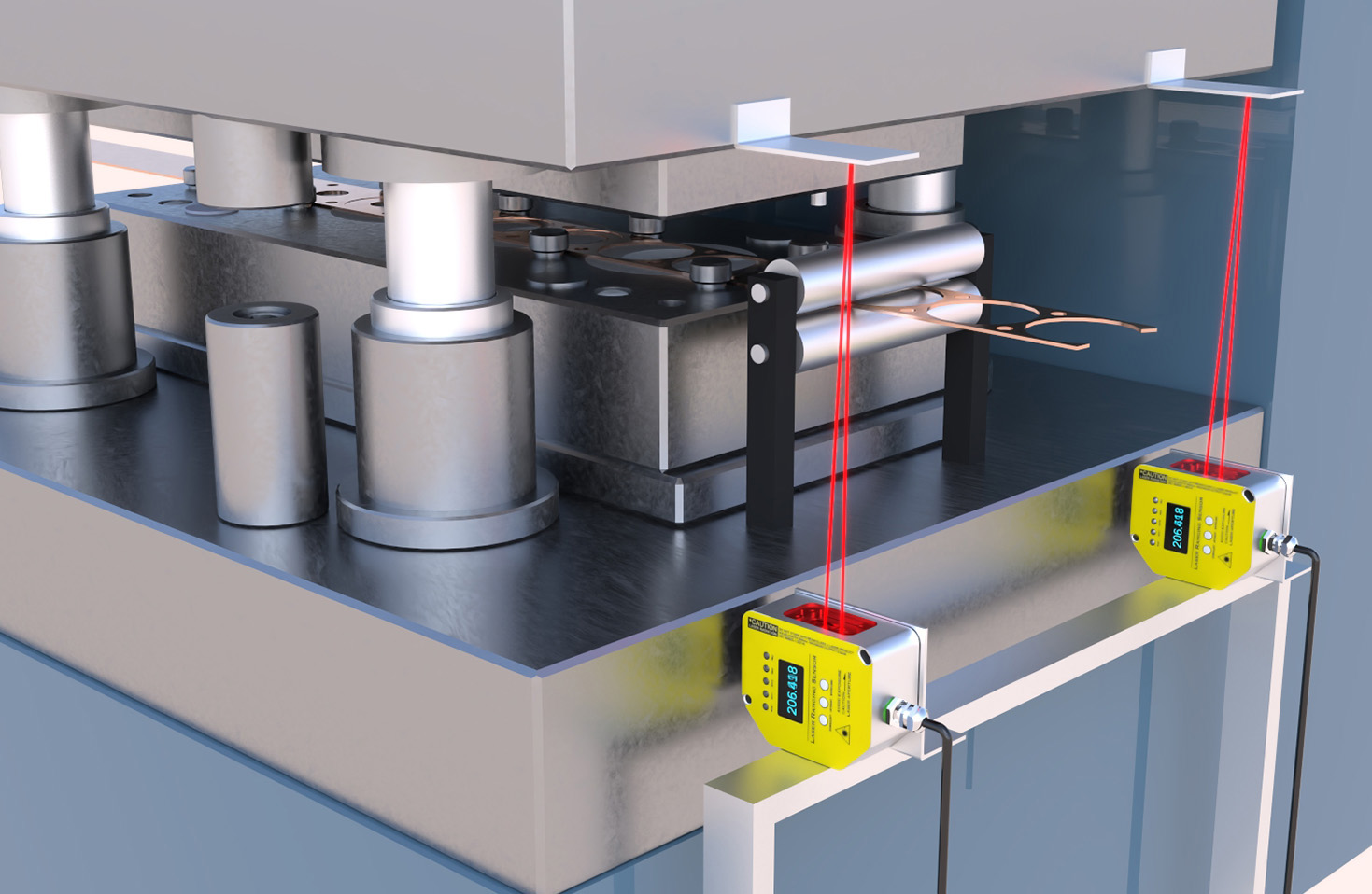
Begin by ensuring power is disconnected to prevent short circuits or damage. Connect the power supply wires: attach the brown wire (or labeled V+) to the positive DC terminal and the blue wire (or labeled V-) to the negative DC terminal. Use appropriate wire gauges as per the sensor’s current rating, usually between 100-200 mA. Secure connections with crimp terminals or screw clamps to avoid loose contacts, which can cause signal noise or failure.
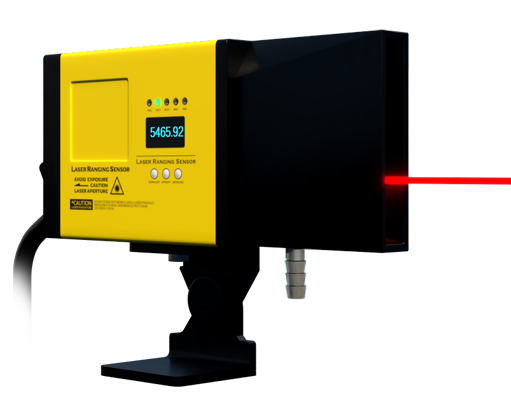
Next, handle the output connection. The black wire is typically the switching output (NPN or PNP). For an NPN (sinking) sensor, the output connects to the load (e.g., PLC input) and then to positive voltage; for a PNP (sourcing) sensor, it connects to the load and then to ground. Confirm your controller’s input compatibility—some PLCs require NPN, while others use PNP. If your sensor has a second output (e.g., white wire), it might be for a complementary signal or alarm function; refer to the manual for configuration.
After wiring, consider environmental factors. Laser sensors are sensitive to ambient light, dust, and vibrations. Install the sensor in a stable location, away from direct sunlight or other strong light sources. Use shielding or enclosures if necessary. Adjust the sensor’s sensitivity and response time via potentiometers or teach-in buttons, following manufacturer guidelines. For example, set the sensing distance by aligning the laser beam with the target and fine-tuning until the indicator LED shows stable detection.
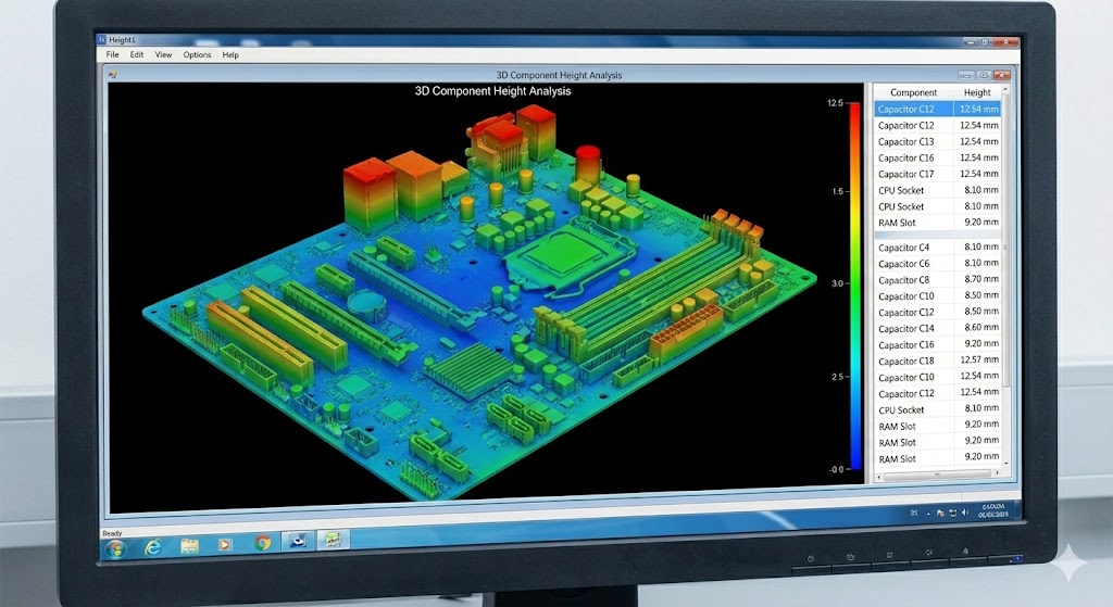
Testing is critical. Reapply power and observe the sensor’s status LED. Perform a functional test by placing an object within the sensing range; the output should activate (e.g., LED change, relay click). Measure the output voltage with a multimeter to ensure it matches expected levels (e.g., near 0V when off, and supply voltage when on). Integrate the sensor with your control system, such as a PLC or microcontroller, and verify data acquisition through software monitoring.
Common pitfalls include incorrect polarity, voltage mismatches, and electromagnetic interference (EMI). Use shielded cables for long runs and keep signal wires away from power lines. Ground the sensor housing if specified. For complex setups, like daisy-chaining multiple sensors or using analog outputs (e.g., 4-20 mA for distance measurement), consult advanced manuals and ensure proper isolation.
In summary, connecting a laser sensor involves careful planning, adherence to electrical standards, and thorough testing. Always prioritize safety by following lockout-tagout procedures and wearing protective gear. By mastering these steps, engineers can enhance system precision and longevity in applications from automation to quality control.