Proximity speed sensors, often referred to as proximity sensors or inductive proximity sensors when used for rotational speed detection, are fundamental components in modern industrial automation and machinery monitoring. Their primary function is to detect the presence, absence, or passage of a metallic target without physical contact, thereby enabling precise measurement of rotational or linear speed. The core principle hinges on electromagnetic induction, offering robustness, reliability, and longevity in harsh environments where mechanical wear or contamination is a concern.
The operational principle of an inductive proximity sensor used for speed sensing is elegantly straightforward. The sensor itself contains a coil wound around a ferrite core, which is part of an oscillator circuit. When energized, this oscillator generates a high-frequency electromagnetic field that radiates from the active face of the sensor. In the absence of a conductive (typically ferrous) metal target, the oscillator operates at a specific, stable amplitude. When a metallic target, such as a gear tooth, key on a shaft, or a dedicated trigger wheel, enters this electromagnetic field, eddy currents are induced on the surface of the target. These eddy currents draw energy from the oscillator circuit, causing a measurable drop in the oscillation amplitude. An integrated evaluation circuit within the sensor detects this amplitude change and triggers a solid-state switch, producing a clean, digital output signal—often a transistor switching from OFF to ON (PNP or NPN configuration).
For speed measurement, this process is repeated cyclically. Consider a gear mounted on a rotating shaft, with a proximity sensor positioned facing the gear teeth. As each tooth passes the sensor face, it triggers an output pulse. The time interval between successive pulses is inversely proportional to the rotational speed. By counting the number of pulses over a known time period, the rotational speed (RPM - Revolutions Per Minute) can be accurately calculated using the formula: RPM = (Pulse Count per Time Unit) / (Number of Targets per Revolution) (Time Conversion Factor). For instance, a 60-tooth gear generating 300 pulses in one second translates to 5 revolutions per second, or 300 RPM.
Key design and selection parameters are critical for optimal performance. The sensing distance, or nominal range, is specified by the manufacturer and is typically a few millimeters for standard sensors; the target must pass within this range to be detected reliably. The target material significantly affects performance; ferrous steels provide the longest sensing ranges, while non-ferrous metals like aluminum or copper require reduced ranges. The size and shape of the target must also be appropriate; as a rule, the target should be at least equal to the sensor's face diameter. For gear sensing, the gear module and tooth profile must be compatible to ensure a clear and unambiguous signal for each tooth.
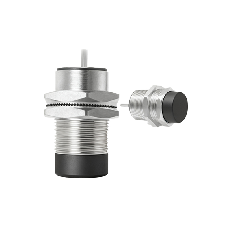
The output signal is a cornerstone of its integration. The clean, fast-switching digital signal (e.g., 24V DC) is ideal for direct connection to programmable logic controllers (PLCs), frequency counters, tachometers, or dedicated speed monitoring modules. This enables a wide array of applications beyond simple speed readout, including overspeed/underspeed trip protection, zero-speed detection for conveyor belts, synchronization control in multi-motor drives, and torsional vibration analysis by examining the pulse period jitter.
Compared to other speed sensing technologies like optical encoders or Hall-effect sensors, inductive proximity sensors offer distinct advantages. They are inherently rugged, with no moving parts and often housed in robust, sealed metal or polymer bodies rated for IP67 or higher, making them resistant to dust, oil, coolant, and mechanical vibration. They are unaffected by ambient light, dirt (provided it is non-metallic), and can operate in a wide temperature range. Their primary limitation is that they only detect conductive metals, and the sensing range is relatively short.
In practical industrial applications, these sensors are ubiquitous. They monitor motor and pump shaft speeds for predictive maintenance, preventing catastrophic failure by detecting speed deviations indicative of load changes or coupling damage. On production lines, they control the speed synchronization of rollers in printing, packaging, and web handling machinery. In automotive manufacturing, they verify the rotational speed of wheels on test stands. In wind turbines, they provide critical overspeed protection for the rotor.
Installation and commissioning require attention to detail. Proper mounting, with adequate clearance around the sensor, is essential to avoid false triggers from surrounding metal structures (a phenomenon known as flanking). Electrical wiring must follow guidelines for supply voltage and load current, and output wires are often shielded to prevent electromagnetic interference (EMI) from corrupting the signal. Regular maintenance is minimal but should include checking for physical damage, buildup of metallic debris on the sensor face, and verifying the stability of the output signal.
In conclusion, the proximity speed sensor is a workhorse of industrial measurement. Its non-contact, inductive operating principle provides a highly reliable method for converting mechanical motion into an electrical signal for speed quantification