Proximity sensors are indispensable components in modern industrial automation, providing non-contact detection of metallic or non-metallic objects. Correct wiring is fundamental to ensuring reliable operation, safety, and longevity of these sensors within a control system. This guide details standard wiring methodologies, best practices, and critical considerations for engineers and technicians.
Proximity sensors are broadly categorized by their output type: two-wire, three-wire, and four-wire configurations. Each type has distinct wiring requirements and operational characteristics.
Two-Wire AC/DC Sensors
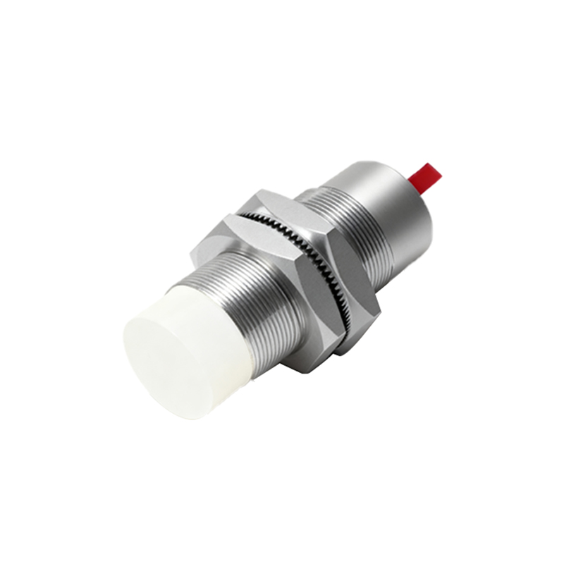
The simplest configuration, two-wire sensors, are connected in series with the load (e.g., a PLC input or relay). They function similarly to a switch. For AC models, the two wires (typically brown and blue) connect directly to the phase (L) and load. DC models connect to the positive and load lines. A critical consideration is the residual current or leakage current. When the sensor is in the "off" state, a small current still flows. This residual current must be lower than the holding current of the connected load (like a relay) to prevent unintended activation. Always verify the sensor's specifications against the load's minimum operating current.
Three-Wire DC Sensors (NPN vs. PNP)
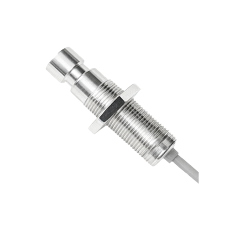
This is the most common configuration in DC systems, offering superior performance with separate power supply, output, and ground wires. The core distinction lies in the output transistor type, which defines the switching logic and wiring.
PNP (Sourcing) Sensors: The output wire (usually black) switches the positive voltage to the load. The wiring sequence is: Brown wire to DC+, blue wire to DC-, and the black output wire to the load. The load's other terminal is then connected to DC-. PNP sensors are often described as "sourcing" because they provide positive voltage to the load.
NPN (Sinking) Sensors: The output wire switches the ground connection to the load. The wiring is: Brown to DC+, blue to DC-, and the black output wire to the load. The load's other terminal is connected to DC+. NPN sensors "sink" current to ground.
Mixing PNP and NPN sensors incorrectly with a PLC's input card is a common error. Most PLCs have input cards designed for either sinking (PNP-compatible) or sourcing (NPN-compatible) logic. Always match the sensor type to the input module specification.
Four-Wire Sensors (Dual Output)
These sensors incorporate both a normally open (NO) and a normally closed (NC) output, typically in a PNP+NPN combination within the same housing. They provide wiring flexibility for control logic. The standard wire colors are often brown (DC+), blue (DC-), black (NO output), and white (NC output). The wiring principle follows the same rules as three-wire sensors for each respective output channel.
Shielded Cables and Noise Immunity
In electrically noisy environments (e.g., near variable frequency drives, motors, or welding equipment), using shielded cables is strongly recommended. The cable shield, typically a braided or foil layer, should be grounded at only one end—usually at the control panel side—to prevent ground loops. This practice effectively drains electromagnetic interference (EMI) away from the signal wires.
Wiring Best Practices and Safety
1. Power Disconnect: Always isolate and lock out/tag out power before beginning any wiring work.
2. Consult Datasheets: Always refer to the manufacturer's datasheet for the specific model's wiring diagram, voltage ratings, and output current limits.
3. Correct Polarity: For DC sensors, reversing polarity can cause permanent damage. Double-check connections.
4. Load Compatibility: Ensure the sensor's maximum switching current and voltage are not exceeded by the connected load. Use an intermediate relay for high-current loads.
5. Short-Circuit Protection: While many modern sensors have built-in protection, incorporating a fast-acting fuse (1-2A) in the supply line is a prudent safety measure.
6. Wire Management: Use conduits or cable trays. Keep sensor cables separated from high-power AC lines to minimize inductive coupling and noise.
7. Testing: After wiring, use a multimeter to verify voltage levels at the output under both target-present and target-absent conditions before integrating into the full system.
Troubleshooting Common Wiring Issues
Sensor Not Powering On: Check supply voltage presence and polarity.
Intermittent Operation: Often caused by loose connections, damaged cables, or electrical noise. Inspect connections and consider