In the field of electrical engineering, laser sensors have become indispensable tools for precise measurement and testing, particularly when it comes to analyzing phase in various systems. Phase testing is crucial for ensuring the proper functioning of electrical circuits, motors, and communication devices, as it relates to the timing and synchronization of signals. Laser sensors offer a non-contact, high-accuracy method to measure phase shifts, making them ideal for applications where traditional probes might interfere with the system or fail to provide sufficient resolution.
To begin testing phase with a laser sensor, one must first understand the basic principles involved. Laser sensors typically operate by emitting a coherent light beam toward a target, such as a rotating shaft or vibrating surface. The reflected light is then analyzed to detect changes in position, displacement, or frequency. For phase measurement, the sensor captures the timing of these changes relative to a reference signal. This process often involves using interferometric techniques, where the interference pattern between the emitted and reflected beams reveals phase differences. In electrical systems, phase is commonly expressed in degrees or radians, indicating the offset between waveforms like voltage and current.

The setup for phase testing requires careful calibration and alignment. Start by selecting an appropriate laser sensor based on the application's requirements, such as range, resolution, and environmental conditions. For instance, in motor testing, a laser Doppler vibrometer might be used to measure vibrations and derive phase information related to rotational speed. Connect the sensor to a data acquisition system, such as an oscilloscope or specialized phase analyzer, ensuring that the reference signal is properly synchronized. Position the sensor perpendicular to the target surface to minimize errors from angular misalignment. It's also essential to account for factors like ambient light, temperature fluctuations, and surface reflectivity, which can affect the sensor's accuracy.
Once the system is configured, the testing procedure involves generating a stimulus, such as an electrical signal or mechanical vibration, and using the laser sensor to capture the response. For example, in testing the phase of an AC circuit, apply a known voltage waveform and use the sensor to measure the resulting current waveform's timing. The phase difference can be calculated by comparing the zero-crossing points or using Fourier transform methods to analyze the frequency domain. Laser sensors excel here due to their high sampling rates and minimal intrusion, allowing for real-time monitoring without loading the circuit. In industrial settings, this enables predictive maintenance by detecting phase imbalances that could indicate faults like worn bearings or misaligned components.
Data analysis is a critical step in phase testing with laser sensors. Modern sensors often come with software that processes the raw data to extract phase information, displaying results in graphs or numerical formats. Engineers should look for consistency in measurements, checking for anomalies that might signal sensor drift or external interference. Statistical tools, such as averaging multiple readings, can enhance reliability. Additionally, validating the results against known standards or using redundant measurement methods helps ensure accuracy. For instance, in power quality analysis, phase angles measured with laser sensors can be cross-checked with clamp meters or power analyzers to confirm system integrity.
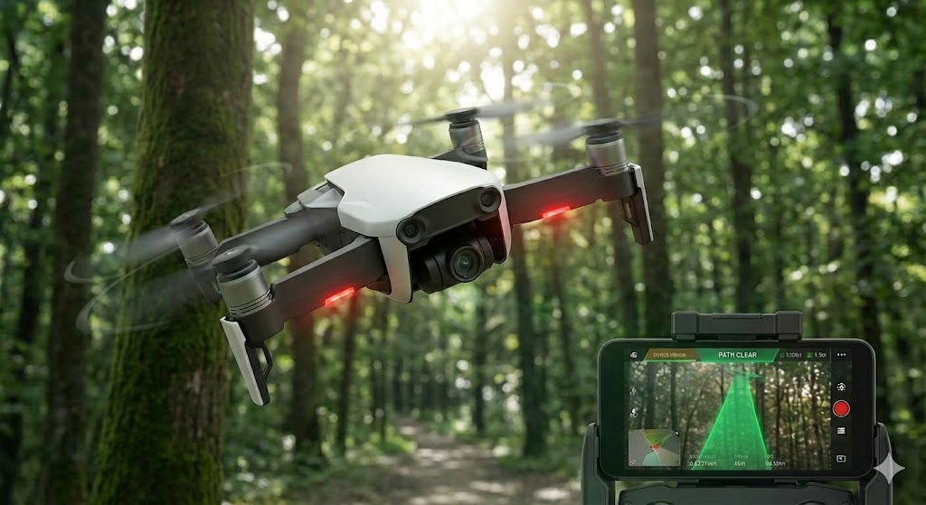
Applications of laser sensor-based phase testing span across various industries. In renewable energy, it's used to optimize the performance of wind turbines by monitoring blade vibrations and phase synchronization. In telecommunications, laser sensors assist in aligning optical fibers to maintain signal coherence. Automotive engineers rely on them for testing engine timing and transmission systems. The non-contact nature of laser sensors makes them particularly valuable in hazardous or high-speed environments, where physical probes could pose safety risks or introduce errors. As technology advances, integration with IoT and AI systems is enabling automated phase monitoring, leading to smarter, more efficient electrical networks.
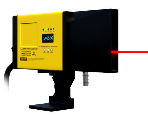
Despite their advantages, challenges exist when using laser sensors for phase testing. High initial costs, sensitivity to environmental conditions, and the need for specialized training can be barriers. However, ongoing developments in sensor miniaturization, cost reduction, and user-friendly interfaces are making these tools more accessible. Best practices include regular maintenance, such as cleaning lenses and updating firmware, along with thorough documentation of testing protocols. By adhering to these guidelines, engineers can leverage laser sensors to achieve precise phase measurements, driving innovation and reliability in electrical engineering projects.
In summary, testing phase with laser sensors is a sophisticated yet practical approach that enhances accuracy and efficiency in electrical systems. By understanding the principles, following proper setup procedures, and analyzing data effectively, professionals can harness this technology to improve performance and troubleshoot issues. As the demand for precision grows in fields like automation and energy management, laser sensors will continue to play a pivotal role in phase testing, contributing to safer and more reliable engineering solutions.