In the realm of industrial automation and control systems, proximity sensors are fundamental components for detecting the presence or absence of an object without physical contact. Among the various specifications and terminologies associated with these devices, "DC NO" is a critical designation that engineers and technicians must comprehend for proper system integration and troubleshooting. This article delves into the meaning, functionality, and application considerations of DC NO in proximity sensors.
Decoding the Terminology: DC and NO
The term "DC NO" is an abbreviation that combines two distinct electrical concepts: power supply type and output contact configuration.
1. DC: This stands for Direct Current. It specifies the type of power supply required to operate the sensor. A DC proximity sensor is designed to be powered by a direct current voltage source, commonly 10-30 VDC in industrial settings (with 12 VDC and 24 VDC being the most prevalent). DC sensors are widely favored for their compatibility with programmable logic controllers (PLCs), faster switching speeds, and generally longer operational life compared to some AC models.
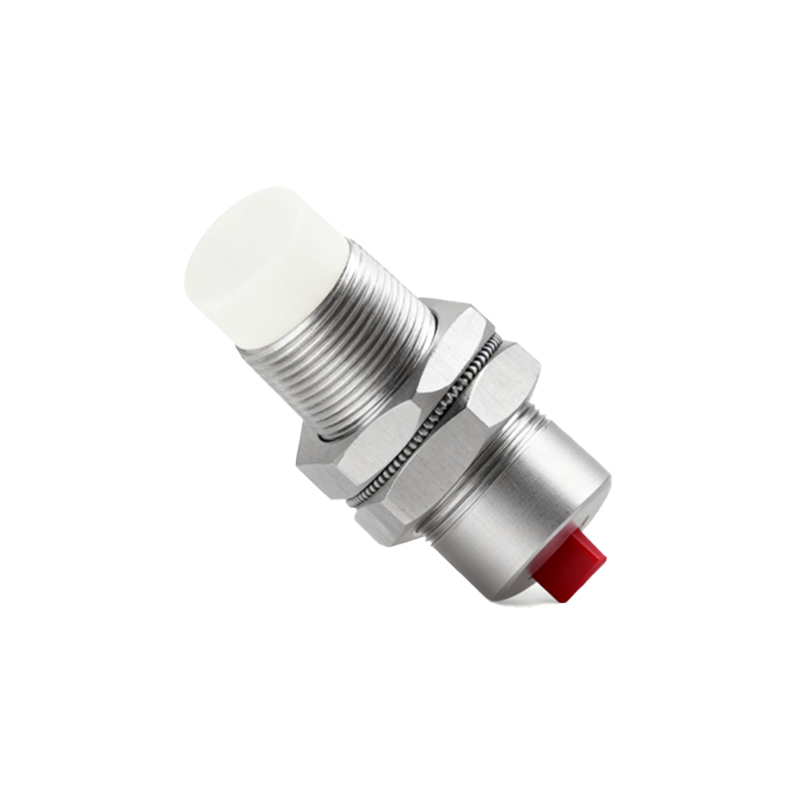
2. NO: This stands for Normally Open. This describes the state of the sensor's output switch (typically a solid-state transistor or a relay contact) when the sensor is in its non-actuated or "normal" condition—that is, when no target is within its detection range. In an NO configuration, the output circuit is open, meaning no current flows through the output terminals under normal conditions. When a target enters the sensing field, the sensor activates and closes this output circuit, allowing current to flow. This action is akin to pressing a momentary push-button switch that is normally open.
Therefore, a DC NO proximity sensor is a device powered by direct current that provides a switched output signal which is open when idle and closes upon detecting a valid target.
How a DC NO Proximity Sensor Operates
Internally, a typical inductive or capacitive DC NO sensor contains an oscillator circuit, a trigger stage, and an output switching component, usually an NPN or PNP transistor. When powered (DC voltage applied), the oscillator generates a high-frequency electromagnetic field at the sensor's active face. In the absence of a target, the output transistor is in an "off" state, maintaining an open circuit between the output wire (often the black wire) and the common or supply voltage wire. This is the "Normal Open" state.
When a metallic target (for inductive sensors) or a material with sufficient dielectric constant (for capacitive sensors) enters the detection zone, it dampens or alters the oscillator's field. This change is detected by the trigger circuit, which subsequently switches the output transistor "on." This action effectively closes the circuit between the output and common terminals, allowing load current to pass. The connected device (e.g., a PLC input, a relay coil, an indicator lamp) is thus energized.
Wiring and Circuit Representation
In electrical schematics, the output of a DC NO sensor is represented by a switch symbol that is open. A standard 3-wire DC sensor will have:
Brown Wire: Connected to the positive DC supply voltage (+V).
Blue Wire: Connected to the negative DC supply voltage (0V or Common).
Black Wire: The output signal line. In an NO configuration, this line will be at a high impedance (effectively disconnected) when idle. Upon detection, it will switch to either connect to +V (for a PNP, sourcing type) or to 0V (for an NPN, sinking type).
The load is connected between the black output wire and the opposite supply rail. For a PNP NO sensor, the load is connected between the black wire and 0V. For an NPN NO sensor, the load is connected between the black wire and +V.
Key Applications and Advantages of DC NO Configuration
The choice of a DC NO sensor is driven by specific control logic and safety requirements:
Safety-Critical "Stop" Conditions: NO contacts are often used in safety circuits where a broken wire or loss of power must result in a "stop" or "safe" state. Since the circuit is normally open, any failure that opens the circuit (like a wire break) mimics the normal, non-actuated state, typically halting a machine.
Energy Efficiency: In applications where the sensor remains in the non-detected state for long periods, an NO output consumes no power through the load, enhancing energy savings.
PLC Input Compatibility: Many PLC digital input cards are designed to read a "high" signal (24V) as TRUE or ON. A PNP-type DC NO sensor provides this high signal only upon detection, making it a perfect fit.
Controlling Relays and Contactors