In industrial automation and control systems, the integration of proximity sensors with contactors is a fundamental yet critical wiring task. This guide provides a detailed, step-by-step explanation of how to properly wire a standard inductive or capacitive proximity sensor to control a contactor, ensuring reliable operation in machinery, conveyor systems, and safety interlocks.
A proximity sensor is a non-contact device that detects the presence or absence of an object within its sensing range. Common types include inductive (for metals) and capacitive (for various materials). Its output is typically a switched signal, either PNP (sourcing) or NPN (sinking). A contactor is an electrically controlled switch used for switching a power circuit, similar to a relay but designed for higher current loads. The core objective is to use the sensor's output signal to energize or de-energize the contactor coil, thereby controlling a high-power load like a motor or heater.
Key Components and Specifications
Before wiring, verify component specifications:
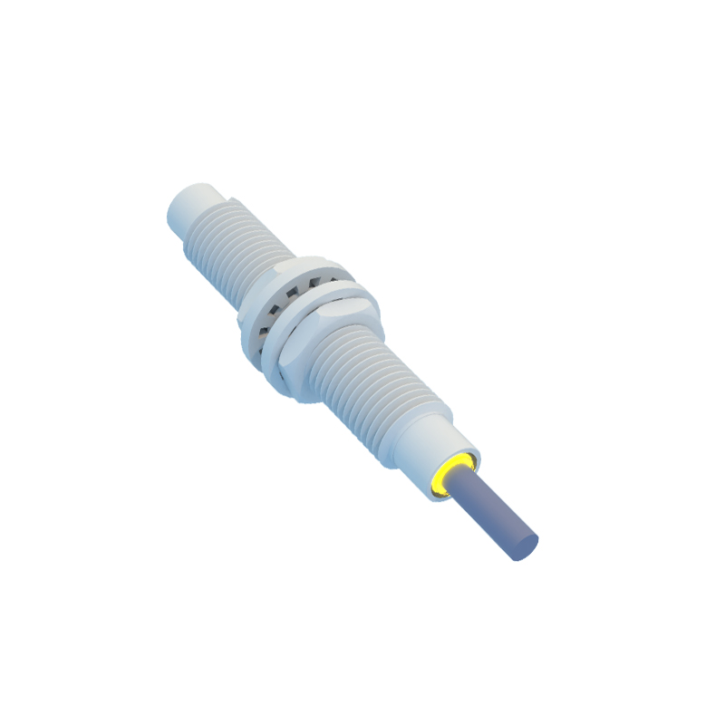
1. Proximity Sensor: Check its operating voltage (common: 10-30V DC), output type (PNP/NPN, NO/NC), and current rating.
2. Contactor: Identify the coil voltage (e.g., 24V DC, 120V AC, 230V AC) and terminal designations (A1/A2 for coil, L1/T1, L2/T2, etc., for main contacts).
3. Power Supply: Select a suitable DC or AC power source matching the sensor and contactor coil requirements. Using a common voltage for both simplifies wiring.
4. Protection Devices: Consider adding a fuse or circuit breaker for overcurrent protection and a suppression diode (for DC coils) or RC snubber (for AC coils) across the contactor coil to mitigate voltage spikes.
Standard Wiring Procedure (Using a 24V DC PNP Normally Open (NO) Sensor and a 24V DC Coil Contactor)
This configuration is prevalent in modern control panels. The principle is to use the sensor as a switch in the control circuit powering the contactor coil.
Step 1: Power Connections.
Connect the positive terminal (+24V) of the DC power supply to the brown wire (or +V terminal) of the PNP proximity sensor.
Connect the negative terminal (0V) of the DC power supply to the blue wire (or 0V terminal) of the sensor AND to one terminal of the contactor coil (typically A2). This establishes a common negative/return path.
Step 2: Sensor Output to Contactor Coil.
Connect the black wire (or output signal wire) of the PNP sensor to the remaining terminal of the contactor coil (typically A1). When a metal object enters the sensing range, the PNP sensor switches its output to +24V, supplying power to the coil and energizing the contactor.
Step 3: Load Power Circuit.
Wire the main power to be controlled (e.g., 3-phase AC for a motor) through the contactor's main power contacts (L1-T1, L2-T2, L3-T3). The control circuit (sensor/coil) is thus completely separate from the load power circuit, enhancing safety.
Step 4: Verification.
Apply power. The sensor's indicator LED should illuminate when an object is detected. Simultaneously, you should hear an audible click from the contactor as it pulls in, and the main contacts close to power the load.
Important Variations and Considerations
NPN Sensor Wiring: For an NPN sensor, the output switches the 0V (negative) line. The wiring differs: Connect the sensor's output to the coil's A2 terminal, while A1 is connected directly to +24V. The common negative from the power supply connects to the sensor's blue wire.
Using a Normally Closed (NC) Sensor: An NC sensor breaks the circuit when an object is detected. This is often used for safety stop applications. The wiring is similar, but the logic is inverted.
AC Coil Contactors: If the contactor coil operates on AC (e.g., 120V AC), and the sensor is DC, an intermediate DC relay is often required. The DC sensor controls the relay coil, and the relay's contacts (rated for AC) then switch the AC power to the contactor coil.
Interfacing with PLCs: In more complex systems,