Proximity sensors are indispensable components in modern industrial automation, robotics, and countless electronic devices. Their ability to detect the presence or absence of an object without physical contact offers unparalleled reliability, speed, and longevity. This article delves into the core operating principles of the main types of proximity sensors, using clear diagrams to illuminate the underlying technology.
1. Inductive Proximity Sensors
The most common type for metal detection, inductive sensors operate on the principle of electromagnetic induction. As shown in Diagram 1, the sensor's core contains an oscillator circuit that generates a high-frequency electromagnetic field at its active face. When a metallic target enters this field, eddy currents are induced on the target's surface. This causes a load on the oscillator, leading to a reduction in its oscillation amplitude. This change is detected by a threshold circuit, which subsequently triggers a solid-state output switch (e.g., NPN or PNP transistor). Key points from the diagram: the oscillator coil, the damping effect of the eddy currents in the target, and the signal processing unit. These sensors are ideal for harsh environments and can detect only conductive materials, primarily metals.
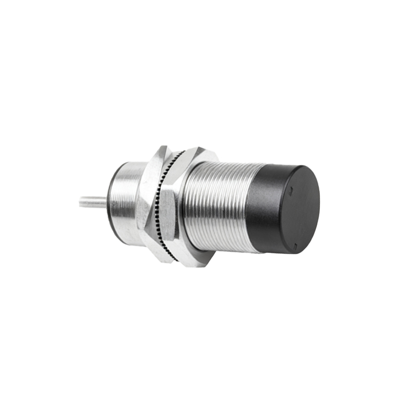
2. Capacitive Proximity Sensors
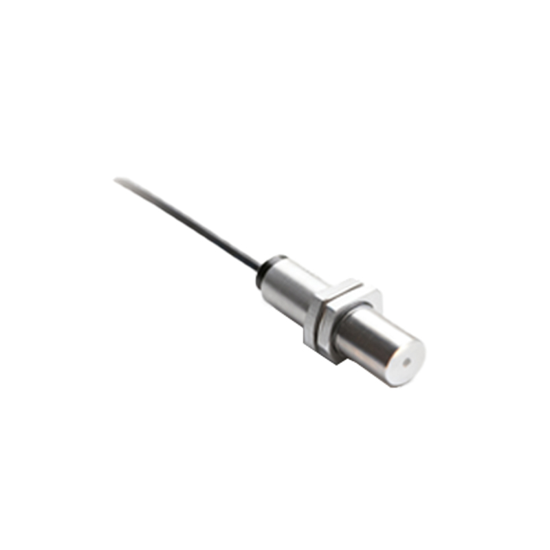
Capacitive sensors can detect both metallic and non-metallic materials, including liquids, powders, and plastics. Their principle, illustrated in Diagram 2, is based on capacitance change. The sensor face forms one plate of a capacitor, with the target object acting as the other plate, and the air gap as the dielectric. The internal oscillator circuit is tuned so that it does not oscillate without a target. When an object approaches, it increases the effective capacitance of the system. Once the capacitance reaches a preset threshold, the oscillator begins to oscillate. This oscillation is then processed to change the output state. The diagram typically highlights the electrode configuration and the electric field lines extending to the target. Sensitivity adjustments allow these sensors to ignore certain materials or detect through thin non-metallic barriers.
3. Ultrasonic Proximity Sensors
These sensors use sound waves beyond the human hearing range. Diagram 3 depicts the two main variants: through-beam and diffuse-reflective (or proximity) modes. In the diffuse mode, a single transducer acts as both transmitter and receiver. It emits a burst of ultrasonic pulses. If an object is within range, these pulses are reflected back to the sensor. An internal timer measures the time between emission and reception of the echo. Using the known speed of sound, the sensor calculates the distance to the object. An output is triggered when this distance falls below a set threshold. The diagram clearly shows the sound wave cone and the echo path. These sensors are excellent for detecting objects of varying color or transparency and are less affected by dust or ambient light.
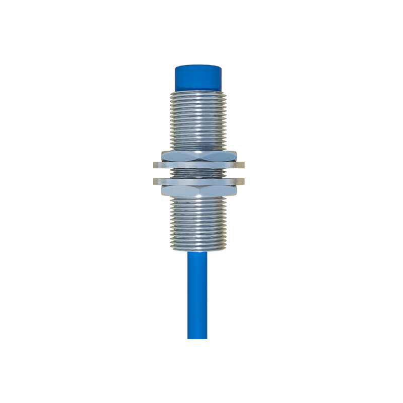
4. Photoelectric Sensors
While often used for longer ranges, photoelectric sensors function as precise proximity devices in diffuse (proximity) mode. As per Diagram 4, the sensor contains a light emitter (usually LED - infrared, red, or laser) and a receiver. The emitted light strikes a target and is scattered. Some of this scattered light returns to the receiver. The intensity of the received light is evaluated. When a target comes close enough to reflect sufficient light intensity, the output switches. The diagram emphasizes the light path and the scattering effect. Advanced versions use background suppression technology to trigger based on the angle of reflected light rather than intensity, allowing for very precise detection independent of the object's color or reflectivity.
5. Magnetic Proximity Sensors (Reed Switches/Hall Effect)
These detect the presence of a permanent magnet. Diagram 5a shows a reed switch: two ferromagnetic, sealed reeds in a glass tube. When a magnet approaches, the reeds magnetize and attract each other, making contact to close a circuit. Diagram 5b illustrates the Hall Effect principle: a semiconductor element through which a constant current flows. When exposed to a magnetic field from an approaching magnet, the Lorentz force deflects charge carriers, generating a voltage difference (Hall voltage) perpendicular to the current flow. This voltage is amplified to trigger an output. These sensors are used for position detection in cylinders and for low-power, sealed applications.
Key Takeaways from the Diagrams:
Each diagram serves to visualize the invisible: electromagnetic fields, capacitance fields, sound waves, and light beams. The common thread is the disturbance of a generated field or signal by a target object. This disturbance is converted into an electrical signal through precise electronic circuitry. Understanding these diagrams is crucial for selecting the right sensor. Consider the target material, required sensing distance, environmental conditions (dust, moisture, EMI), and output requirements.
In summary, proximity sensors are marvels of applied physics. From the electromagnetic damping in inductive sensors to the time-of-flight calculation in ultrasonic models, each type translates a physical principle into a reliable