Two-wire proximity sensors are widely used in industrial automation for detecting the presence or absence of objects without physical contact. These sensors are known for their simplicity, cost-effectiveness, and ease of installation. Unlike three-wire or four-wire sensors, two-wire models integrate the power supply and signal output into a single circuit, reducing wiring complexity and space requirements. This article provides a comprehensive guide to the wiring diagram of two-wire proximity sensors, covering principles, installation steps, and common applications.
The basic principle of a two-wire proximity sensor involves connecting it in series with the load (e.g., a PLC input module, relay, or indicator). The sensor operates by drawing a small leakage current when idle and increasing current flow when activated. Typically, two-wire sensors are available in two configurations: normally open (NO) and normally closed (NC). In a NO configuration, the sensor acts as an open switch when no target is detected, allowing minimal current flow. When a target enters the sensing range, the switch closes, enabling full current to pass through the load. Conversely, an NC configuration works in the opposite manner.
Wiring a two-wire proximity sensor requires attention to voltage polarity and load compatibility. Most two-wire sensors are designed for DC voltage (commonly 10-30V DC), though AC models exist. The wiring diagram is straightforward: connect one wire to the positive power supply terminal and the other to the load, which is then linked to the negative supply. For example, in a DC system, the brown wire (usually positive) is connected to the power source's positive terminal, while the blue wire (usually negative) is attached to the load's input side. The load's output side returns to the power source's negative terminal, completing the circuit. It is crucial to verify the sensor's specifications, as incorrect polarity can damage the device.
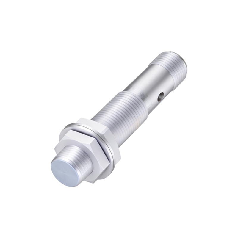
Installation steps begin with selecting an appropriate sensor based on sensing distance, material (inductive for metals, capacitive for non-metals), and environmental conditions. Mount the sensor securely, ensuring the sensing face is aligned with the target path without obstructions. When wiring, use shielded cables to reduce electrical noise interference, especially in high-voltage environments. Maintain proper cable lengths to avoid voltage drop, and follow the manufacturer's diagram precisely. After connections, test the sensor by bringing a target within range and checking the load response. Adjust the sensitivity if the sensor includes a potentiometer for fine-tuning.
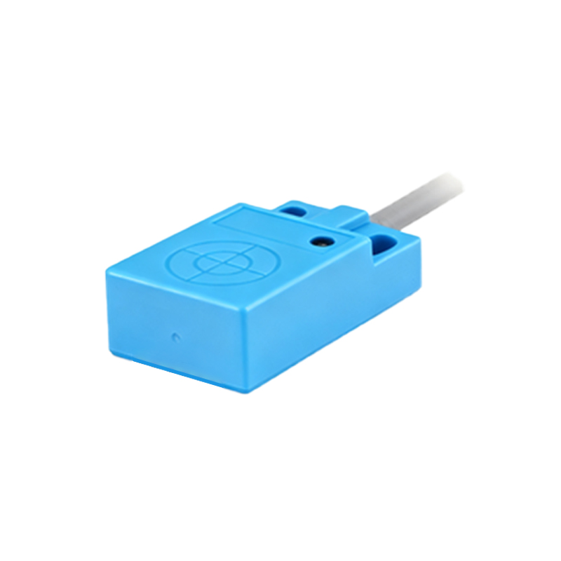
Common applications include conveyor belt systems, where sensors detect objects for counting or positioning; machine safety interlocks, preventing operation when guards are open; and packaging machinery, triggering actuators based on product presence. Two-wire sensors are favored in compact setups due to their minimal wiring, but they may have limitations such as higher residual current (leakage) when off, which can affect low-power loads. To mitigate this, choose sensors with low leakage current or add a bypass resistor.
Troubleshooting wiring issues often involves checking for loose connections, incorrect voltage, or overloaded circuits. Use a multimeter to measure voltage across the sensor and load. If the sensor fails to activate, ensure the target is within the specified sensing range and material compatibility. For false triggers, inspect for environmental factors like vibration, moisture, or electromagnetic interference. Regular maintenance, including cleaning the sensing face and verifying connections, enhances longevity.
In summary, two-wire proximity sensors offer a practical solution for many automation tasks. By understanding the wiring diagram and following best practices, engineers can ensure reliable operation and optimize system performance. Always refer to the sensor's datasheet for specific details, as variations exist among manufacturers and models.