Metal proximity switches are essential components in industrial automation, serving as non-contact sensors for detecting the presence of metallic objects. Ensuring their proper functionality is critical for maintaining operational efficiency and safety in manufacturing, packaging, and machinery systems. This guide provides a systematic approach to testing metal proximity switches, covering preliminary checks, electrical testing methods, and practical troubleshooting steps, all tailored for electrical engineers and maintenance professionals.
Before initiating any tests, perform a visual inspection. Check the sensor housing for physical damage, cracks, or signs of corrosion, especially in harsh environments. Verify that the mounting is secure and properly aligned, as misalignment can cause detection failures. Inspect the cable and connector for wear, fraying, or loose connections, which may lead to intermittent faults. Ensure the sensing face is clean and free from debris, metal chips, or contaminants that could interfere with detection.
Next, confirm the power supply specifications. Metal proximity switches typically operate on DC (e.g., 10-30V DC) or AC voltages, with variants like 2-wire, 3-wire (PNP or NPN), or 4-wire designs. Refer to the datasheet or nameplate for voltage, current, and output type details. Using a multimeter, measure the supply voltage at the switch terminals to ensure it matches the rated value. An unstable or incorrect power supply can cause erratic behavior or failure.
For electrical testing, begin with output verification. For a 3-wire DC proximity switch, identify the wiring: brown (positive), blue (negative), and black (output). With power applied and no target metal present, measure the voltage between the output and negative wires. In a normally open (NO) configuration, the output should be low (near 0V for NPN or high for PNP). Introduce a standard metal target (e.g., mild steel) within the specified sensing distance. The output should switch states—for NPN, voltage rises to near supply level; for PNP, it drops to low. Use an oscilloscope if available to check for clean switching without excessive bounce or delay.
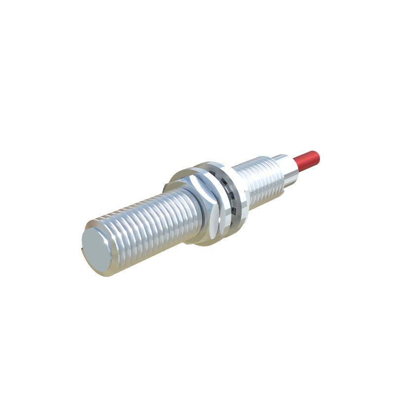
Testing the sensing performance involves evaluating the effective sensing distance. According to IEC 60947-5-2, the nominal sensing distance (Sn) is the theoretical value, while the operational distance should be 0.8-0.9 times Sn to account for tolerances. Gradually move a target toward the sensor until the output activates, noting the distance. Repeat with different target sizes and materials, as factors like material type (steel, aluminum, copper) and size affect sensitivity. Aluminum or non-ferrous metals may reduce the sensing range by up to 50% compared to steel.
For 2-wire AC/DC switches, testing requires caution due to leakage current. With power off, disconnect the load and connect a multimeter in series to measure current flow. When the switch is off, leakage current should be minimal (e.g.,<1.5 mA for AC types). Activate the switch with a metal target; the current should increase to the rated load level. High leakage current can inadvertently keep loads energized, posing safety risks.
Additional diagnostic steps include checking response time and frequency. Use a function generator and oscilloscope to pulse a metal target at high speeds, ensuring the switch can handle the specified switching frequency without missing detections. Monitor for temperature effects, as extreme heat or cold can alter performance. If the switch fails tests, consider environmental factors like electromagnetic interference (EMI) from nearby motors or welders, which may require shielding or relocation.
In summary, testing metal proximity switches involves a combination of visual inspection, electrical measurement, and functional validation. Regular maintenance and testing prevent downtime and ensure reliable automation processes. Always follow manufacturer guidelines and safety protocols when working with industrial sensors.