Metal proximity sensors are essential components in industrial automation, offering reliable detection of metallic objects without physical contact. Understanding their wiring configurations is crucial for ensuring optimal performance and system integration. This article provides detailed wiring diagram examples for common metal proximity sensor types, including two-wire, three-wire, and four-wire models, along with practical considerations for installation and troubleshooting.
Two-Wire AC/DC Sensors:
Two-wire sensors are the simplest to connect, as they function similarly to a switch in series with the load. The wiring diagram typically shows one wire connected to the power supply (L+ for DC or L for AC) and the other to the load, which then returns to the power supply's neutral or ground. For AC sensors, ensure the load current does not exceed the sensor's rated residual current to prevent malfunction. DC models require attention to polarity; incorrect connections may damage the sensor. A typical application involves connecting the brown wire (L+) to positive DC voltage and the blue wire to the load, with the load's other terminal linked to ground. Always refer to the manufacturer's datasheet for specific color codes and ratings.
Three-Wire DC Sensors:
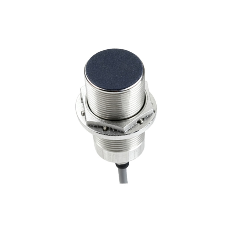
Three-wire sensors are widely used in DC systems due to their separate power and output lines, reducing leakage current effects. The standard wiring diagram includes:
- Brown wire: Connect to DC positive (typically +12V or +24V).
- Blue wire: Connect to DC negative or ground.
- Black wire: Output signal line (normally open or normally closed) connected to the PLC input or relay.
For NPN (sinking) outputs, the black wire switches the load to ground, while for PNP (sourcing) outputs, it switches to positive voltage. Shielding the cable is recommended in electrically noisy environments to prevent false triggering. Always ensure the load impedance matches the sensor specifications to avoid overheating.
Four-Wire Sensors with Dual Outputs:
Four-wire sensors provide two independent outputs, such as one normally open (NO) and one normally closed (NC), allowing flexible control logic. The wiring diagram adds an additional output wire, often white or gray, alongside the standard brown (power), blue (ground), and black (first output). Connect both outputs to separate PLC channels or devices, ensuring the total current draw does not exceed the sensor's capacity. These sensors are ideal for safety circuits or redundant systems where dual signaling is required.
Installation and Troubleshooting Tips:
1. Maintain proper sensing distance: Metal objects should approach within the specified range to avoid unreliable detection.
2. Avoid mutual interference: When mounting multiple sensors, maintain a minimum spacing (usually 2-3 times the sensor diameter) to prevent crosstalk.
3. Check voltage compatibility: Mismatched power supplies can lead to sensor failure. Use stabilized power sources with adequate current capacity.
4. Diagnose common issues: If a sensor fails, verify wiring continuity, measure output voltage under load, and inspect for environmental factors like metal dust or temperature extremes.
5. Implement protective circuits: For inductive loads (e.g., relays), add flyback diodes or surge suppressors to prevent voltage spikes from damaging the sensor.
In summary, correct wiring is fundamental to the functionality of metal proximity sensors. By following standardized diagrams and adhering to manufacturer guidelines, engineers can ensure robust and efficient automation systems. Regular maintenance and systematic troubleshooting further enhance longevity and reliability in industrial applications.