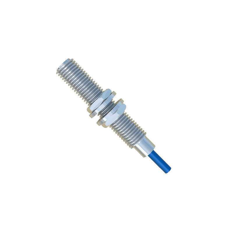
Proximity sensors are widely used in industrial automation, robotics, and safety systems due to their non-contact detection capabilities. Understanding the internal structure of these sensors is crucial for proper selection, installation, and troubleshooting. This article provides a detailed analysis of the typical structure of inductive and capacitive proximity sensors, supported by simplified structural diagrams, and explains their fundamental operating principles.
A standard inductive proximity sensor, designed primarily for detecting metallic objects, consists of several key components housed within a robust casing, usually made of metal (like brass or stainless steel) or polymer materials. The front face contains the active sensing surface. Internally, the core component is a coil wound around a ferrite core. This coil is part of an oscillator circuit. Behind the oscillator circuit lies a trigger circuit and, finally, an output switching stage. The entire assembly is often potted with epoxy resin to provide protection against vibration, moisture, and contaminants. When the sensor is powered, the oscillator generates a high-frequency electromagnetic field at the sensing face. When a metallic target enters this field, eddy currents are induced on the target's surface. This causes a change in the oscillation amplitude or frequency. The trigger circuit monitors this change and, when it reaches a predetermined threshold, activates the output switch (which can be an NPN or PNP transistor, or a relay). The structural diagram clearly shows the layered arrangement: sensing face, coil/oscillator, signal processing unit, and output module, all aligned along the sensor's central axis.
Capacitive proximity sensors share a similar external form factor but have a different internal structure to detect both metallic and non-metallic materials (like plastics, wood, or liquids). Their sensing face typically consists of two concentric electrodes acting as plates of a capacitor. These electrodes are connected to an internal oscillator. The surrounding guard electrode or shield is a critical structural element that focuses the electrostatic field forward and minimizes sensitivity to the sensor's sides, preventing false triggers from the mounting fixture. The internal circuitry is more complex, often involving a reference oscillator and a measurement oscillator. The presence of any material with a dielectric constant different from air alters the capacitance between the electrodes, which in turn changes the oscillator's characteristics. This change is evaluated by the subsequent trigger and output circuits. A structural diagram of a capacitive sensor highlights the electrode arrangement, the shielding, and the comparative circuitry that allows it to distinguish between different material types.
Key structural aspects visible in diagrams include the sensing range, which is determined by the coil/electrode size and oscillator design, and the presence of a hysteresis zone to prevent output chattering when a target is at the detection boundary. The housing design also incorporates features like LED indicators for status and threaded barrels for easy mounting. For advanced models, the structure may include analog output components or digital communication chips for IO-Link functionality, adding another layer to the internal block diagram.
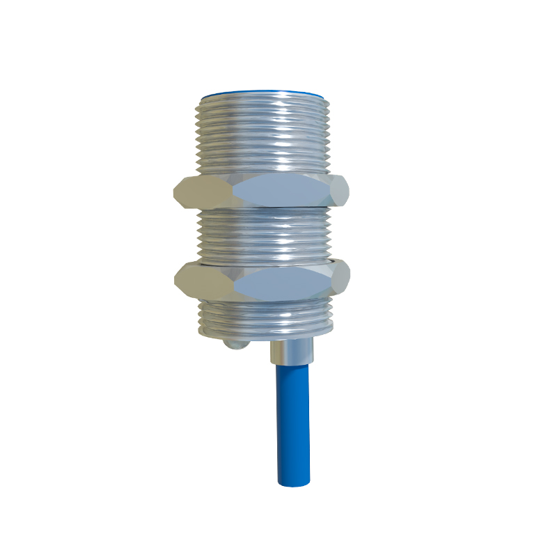
The working principle is intrinsically linked to this physical structure. In inductive sensors, the electromagnetic field's shape defines the sensing profile. In capacitive sensors, the electrode geometry and shielding define the electrostatic field pattern. Understanding the structure helps engineers appreciate factors like flush-mounting versus non-flush mounting. A non-flush (unshielded) inductive sensor has an extended field, offering a longer range but requiring more clearance from metal surroundings. A flush (shielded) sensor has a field focused directly ahead, allowing it to be embedded in metal without triggering, as clearly depicted by the field lines in a structural cross-section.
In conclusion, the internal structure of a proximity sensor is a precise arrangement of electromagnetic or electrostatic components paired with solid-state electronics. Diagrams that delineate these components provide invaluable insight into the sensor's capabilities, limitations, and appropriate application scenarios. Whether for selecting a sensor for a specific material, diagnosing a failure, or designing a machine layout, a firm grasp of the structure behind the sensor is as essential as understanding its electrical specifications.