Proximity sensors are fundamental components in modern industrial automation, robotics, and countless electronic applications. As an electrical engineer, understanding their principles, types, and applications is crucial for designing efficient and reliable systems. This tutorial provides a comprehensive guide to proximity sensors, from basic operation to advanced selection criteria.
What is a Proximity Sensor?
A proximity sensor is a non-contact electronic device that detects the presence or absence of an object within its sensing range without any physical contact. It converts information about the movement or presence of an object into an electrical signal. The key advantage is the absence of mechanical wear and tear, leading to higher reliability and longer service life compared to mechanical limit switches.
Core Operating Principles
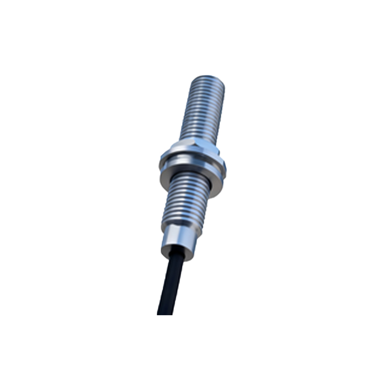
Proximity sensors operate based on different physical principles, primarily:
1. Inductive Sensing: Used for detecting metallic objects (typically ferrous metals like steel and iron). The sensor generates an electromagnetic field. When a metal object enters this field, eddy currents are induced in the object, which causes a change in the sensor's own oscillation amplitude. This change is detected and triggers the output switch.
2. Capacitive Sensing: Can detect both metallic and non-metallic objects (plastics, wood, liquids, powders). The sensor functions like an open capacitor. The approaching object changes the dielectric constant of the space between the sensor's electrodes, altering the capacitance. This change is measured to detect the object.
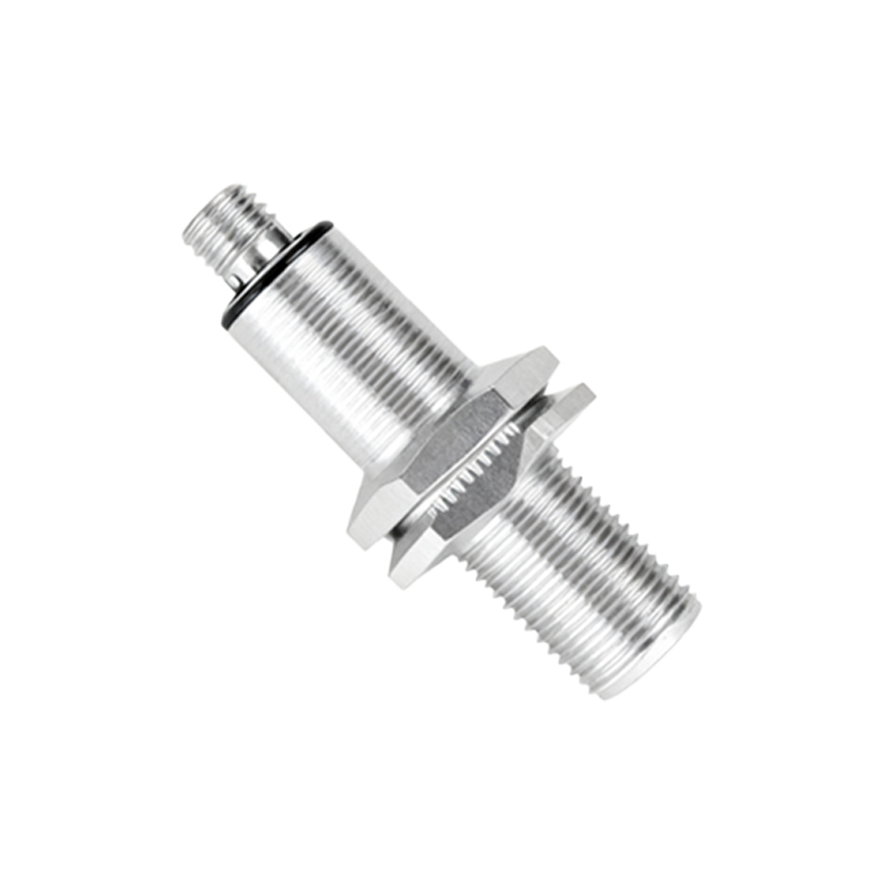
3. Ultrasonic Sensing: Uses sound waves beyond human hearing. The sensor emits ultrasonic pulses and measures the time taken for the echo to return from a target object. This time-of-flight measurement calculates distance, making it effective for level detection and presence sensing of varied materials.
4. Photoelectric Sensing: Utilizes a light emitter (usually LED) and a receiver. It detects objects by interpreting changes in the received light signal. Common modes include through-beam (object breaks the beam), retro-reflective (object reflects the beam from a reflector), and diffuse (object reflects the beam directly back to the receiver).
Key Specifications and Selection Criteria
Choosing the right sensor requires careful analysis of application parameters:
Sensing Range: The maximum distance from the sensor face at which a standard target can be reliably detected. Always consider a safety margin (derating).
Output Type: Digital (PNP/NPN transistor, NO/NC) or Analog (4-20 mA, 0-10V). PNP (sourcing) and NPN (sinking) are standard in PLC interfacing.
Repeatability: The consistency of the sensing point under identical conditions. Critical for precision applications.
Response Time/Frequency: How quickly the sensor can react to a change and how many detection cycles it can perform per second.
Environmental Factors: IP (Ingress Protection) rating for dust and water resistance, temperature range, resistance to chemicals, and immunity to electrical noise (EMI).
Target Material: The object's composition (steel, aluminum, plastic, liquid) directly dictates the sensor type (inductive, capacitive, etc.).
Mounting and Size: Flush-mounted (shielded) inductive sensors can be embedded in metal, while non-flush (unshielded) offer longer ranges.
Typical Industrial Applications
Machine Automation: Position verification of parts, end-of-travel detection, and robotic arm positioning.
Material Handling: Object counting on conveyors, jam detection, and pallet presence sensing.
Assembly Lines: Verifying component presence before a process step (e.g., "Is the bottle cap in place?").
Level Control: Detecting fill levels of liquids or bulk solids in tanks using capacitive or ultrasonic sensors.
Safety: Used as part of safety interlock systems to ensure guards are closed.
Installation and Wiring Best Practices
Proper installation is key to optimal performance. Maintain the specified sensing distance from the target. For inductive sensors, ensure the target material and size meet the sensor's specifications. For all sensors, avoid mounting flush with or near other metal surfaces unless specified as shielded. Maintain adequate clearance between multiple sensors to prevent mutual interference (cross-talk). Always follow the manufacturer's wiring diagram. For DC sensors, pay strict attention to polarity (brown wire to +V, blue wire to 0V/common). Use shielded cables in electrically noisy environments and ground the shield properly at one end. Always implement power supply filtering and fusing as recommended.
Troubleshooting Common Issues
No Output/Signal: Check power supply voltage and polarity. Verify the target is within range, of correct material, and size. Inspect for physical damage or contamination on the sensor face.
Intermittent Operation: Often