Laser sensor modules are critical components in modern industrial automation, robotics, and precision measurement systems. Proper wiring is essential to ensure accurate signal transmission, operational safety, and system longevity. This guide provides a detailed, step-by-step approach to wiring a typical laser sensor module, covering electrical connections, interface considerations, and best practices for integration into control systems.
First, identify the module's specifications from its datasheet. Common laser sensor modules operate on DC voltages, typically 12V or 24V, with current consumption ranging from 20mA to 100mA. The output signal type is crucial—it may be digital (e.g., NPN/PNP open-collector, push-pull) or analog (e.g., 0-10V, 4-20mA). Additionally, note the pinout configuration, which usually includes power supply pins (Vcc and GND), output signal pins, and sometimes auxiliary pins for teach-in or diagnostic functions.
Begin by preparing the power supply. Use a regulated DC power source matching the module's voltage rating. Ensure the power supply can deliver at least 20% more current than the module's maximum requirement to handle inrush currents. Connect the positive terminal (Vcc) of the power supply to the module's Vcc pin and the negative terminal (GND) to the module's GND pin. Employ twisted-pair cables for power connections to minimize electromagnetic interference (EMI). For long cable runs, consider using shielded cables and grounding the shield at one end to prevent ground loops.
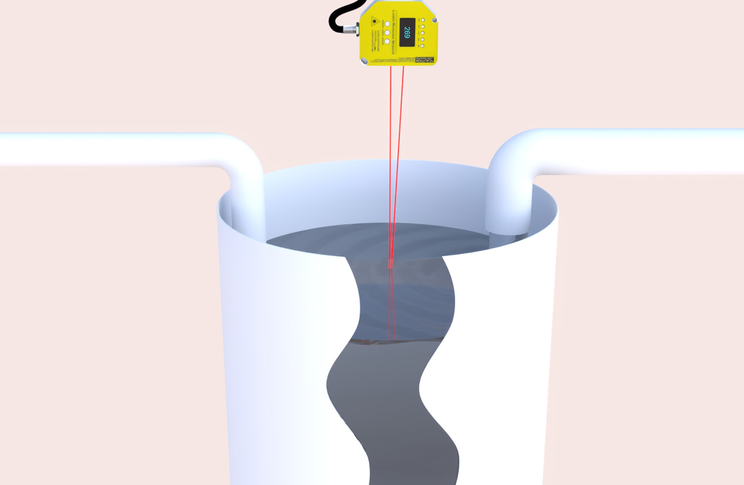
Next, handle the output wiring based on the signal type. For digital NPN output (sinking), the output pin acts as a switch to ground. Connect the output pin to the input of a PLC, microcontroller, or relay. The PLC input should be pulled up to its internal supply voltage through a resistor. For PNP output (sourcing), the output pin switches the positive voltage. Connect it to the PLC input, with the input's common terminal tied to ground. Verify the voltage levels are compatible—most industrial PLCs accept 24V DC inputs.
For analog output modules, wiring involves connecting the output pin to an analog input channel of a controller. If the output is current-based (4-20mA), a precision resistor (e.g., 250Ω) is often placed across the input to convert the current to a voltage signal. Ensure the controller's analog input is configured for the correct range (e.g., 0-10V or 4-20mA). Use separate cables for analog signals and power lines to avoid noise coupling.
Safety precautions are paramount. Always power off the system before making connections. Double-check polarities to prevent reverse voltage damage. Implement fuses or circuit breakers in the power line—a fast-acting fuse rated slightly above the module's operating current is recommended. For modules with laser emission, adhere to laser safety standards (e.g., IEC 60825) by ensuring proper enclosure and interlock mechanisms to prevent accidental exposure.
After wiring, perform a systematic test. Power on the module and observe its indicator LED (if available)—it should illuminate steadily. Test the output by placing an object within the sensing range. Use a multimeter or oscilloscope to verify the output signal matches expectations. For analog sensors, check linearity across the measurement range. If the module features teach-in or configuration buttons, follow the manufacturer's instructions to set parameters like sensing distance or output delay.
Integration into a larger system requires attention to environmental factors. Avoid mounting the module near strong EMI sources like motors or inverters. Ensure the sensing path is free of obstructions and reflective surfaces that could cause false triggers. For harsh environments, select modules with appropriate IP ratings and use conduit or cable glands to protect connections.
In summary, wiring a laser sensor module demands careful planning and adherence to technical specifications. By following these steps—verifying specs, securing power and signal connections, implementing safety measures, and thorough testing—engineers can achieve reliable and precise sensor operation. Consistent practices in wiring not only enhance performance but also reduce downtime and maintenance costs in industrial applications.