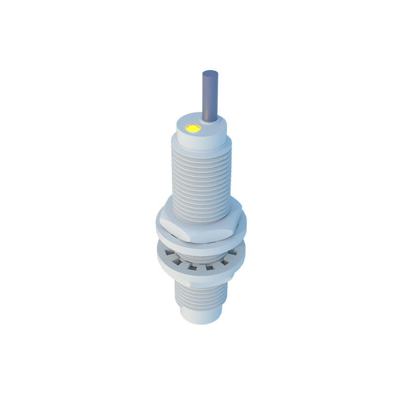
In industrial automation and control systems, proximity sensors are indispensable components for non-contact detection of objects. A critical, yet sometimes overlooked, feature of these sensors is the integrated indicator light. This small LED serves as a vital communication interface between the sensor and the technician, providing immediate visual feedback on the sensor's operational status. A deep understanding of what these lights signify is paramount for efficient installation, commissioning, and maintenance.
Typically, a proximity sensor is equipped with at least one LED indicator. The most common configuration involves a single LED that can display different colors—most frequently green, yellow/amber, and red—or a combination of steady and blinking patterns. Some advanced models may feature two separate LEDs for more granular status reporting. The specific meaning of each color and pattern is defined by the manufacturer and detailed in the sensor's datasheet, but several conventions are widely adopted across the industry.
A steady green light generally indicates that the sensor is powered correctly and is in its normal operating state. For a normally-open (NO) sensor, this often means no target is within the sensing range. When a target enters the detection field, the LED's behavior changes. It may turn off, switch to another color (like yellow), or blink. This change confirms the switching action, allowing a technician to visually verify that the sensor is detecting the object as intended without needing a multimeter or PLC readout. This is invaluable during setup and alignment.
A steady or blinking red light is universally recognized as a warning or error indicator. This can signal several issues: a wiring fault (such as reverse polarity or a short circuit), an overload condition, a sensor malfunction, or an operating environment outside specified parameters (e.g., temperature extremes). A blinking pattern, such as a slow blink versus a rapid flash, often encodes specific error codes. Consulting the manual is essential to decode these patterns accurately.
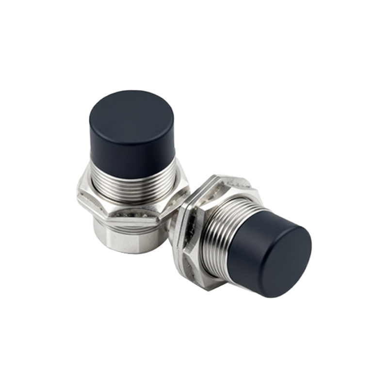
The yellow or amber light often represents an intermediate or special state. In some sensors, it indicates a teach-in mode is active, allowing for the adjustment of sensing parameters. In others, it might signal a weakened output due to a marginal detection scenario, a warning that the sensing face is dirty, or that the sensor is operating in a pulsed mode to reduce heat or energy consumption.
From a practical troubleshooting perspective, the indicator light is the first point of diagnosis. If a machine stops and a proximity sensor is implicated, the technician's first action should be to observe its LED. No light at all suggests a power supply issue—check the voltage, wiring connections, and fuses. A solid red light points towards a sensor or circuit fault. A sensor that shows power (green light) but does not change state when a target is presented indicates a potential problem with alignment, a dirty sensing face, an incorrect sensing distance for the target material, or a failed output stage.
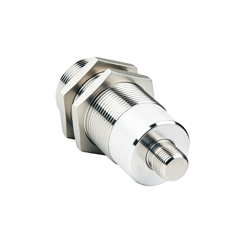
Best practices for utilizing these indicators begin with thorough documentation. Always keep the sensor's manual accessible. During installation, use the indicator to confirm proper alignment and sensing distance before locking the sensor in place. Implement regular preventive maintenance checks where visual inspection of sensor LEDs is part of the routine. A sensor with an intermittently flickering indicator might be an early warning of impending failure or environmental interference.
Furthermore, in safety-critical applications, understanding the indicator's behavior is non-negotiable. A sensor might appear to function (its output may cycle), but a red error light could indicate an internal fault that compromises reliability. Never ignore a persistent error indicator.
In conclusion, the humble indicator light on a proximity sensor is a powerful diagnostic tool. It transforms the sensor from a simple black box into an intelligent device capable of communicating its health and status. By systematically interpreting its language—green for normal operation, red for errors, and yellow for special modes—engineers and technicians can dramatically reduce downtime, accelerate troubleshooting, and ensure the robust and reliable performance of automated systems. Investing time to learn this visual language pays significant dividends in operational efficiency.