In industrial automation and control systems, proximity sensors are indispensable components for non-contact detection of metallic or, in some cases, non-metallic objects. Among the various types, 4-wire DC proximity sensors are particularly common due to their ability to provide both a switched output and a direct power supply connection, often simplifying wiring and improving reliability. Correctly wiring these sensors is crucial for ensuring system safety, accuracy, and longevity. This guide provides a detailed, step-by-step explanation of how to properly connect a 4-wire proximity sensor.
First, it is essential to understand the standard color coding and function of the four wires. While manufacturers may have slight variations, the most common convention for DC sensors is as follows:
Brown Wire: This is the positive supply voltage wire (+V). It must be connected to the positive terminal of your DC power source.
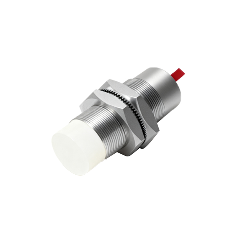
Blue Wire: This is the negative supply voltage wire (0V or Common). It must be connected to the negative terminal or ground of your DC power source.
Black Wire: This is the output signal wire. In a normally open (NO) configuration, this wire will switch to supply voltage (+V) when a target is detected. In a normally closed (NC) configuration, it will switch to 0V when a target is detected.
White Wire: This is often a second output wire or a complementary output. Its function can vary. It may be configured as the opposite state of the black wire (e.g., if black is NO, white might be NC), or it could be used for a specific function like a short-circuit protection alarm output. CRITICAL: Always consult the specific sensor's datasheet or manual to confirm the exact function of the white wire, as it is not universally standardized.
The standard operating voltage for these sensors is typically 10-30V DC. Exceeding this range can cause permanent damage.
Wiring Procedure for a Standard 4-Wire DC Proximity Sensor (Sinking/NPN or Sourcing/PNP):
The wiring differs slightly depending on whether you have a Sourcing (PNP) or Sinking (NPN) sensor. This refers to the type of transistor used in the output stage.
For a Sourcing (PNP) Sensor:
1. Power Connection: Connect the Brown wire to the positive (+) terminal of your DC power supply (e.g., +24V). Connect the Blue wire to the negative (-) terminal or ground (0V) of the power supply.
2. Load Connection: The load (e.g., a PLC input, relay coil, or indicator lamp) is connected between the Black output wire and the negative side of the supply (0V).
3. Operation: When the sensor detects an object, the internal PNP transistor switches, sourcing current from the Brown wire through the Black wire, through the load, and back to the Blue wire/0V. The voltage on the Black wire rises to near the supply voltage (+V).
4. White Wire: Connect the White wire according to its defined purpose in the manual. If it's a complementary output, it would typically be connected to a second load.
For a Sinking (NPN) Sensor:
1. Power Connection: This is identical: Brown to +V, Blue to 0V.
2. Load Connection: The critical difference is that the load is connected between the positive side of the supply (+V) and the Black output wire.
3. Operation: When the sensor detects an object, the internal NPN transistor switches, sinking current from the load, through the Black wire, and back to the Blue wire/0V. The voltage on the Black wire drops to near 0V when active.
4. White Wire: Again, consult the datasheet for its specific connection.
Critical Safety and Best Practices:
1. Always De-energize: Before starting any wiring work, lock out and tag out (LOTO) the main power source to prevent electrical shock or equipment damage.
2. Refer to the Datasheet: Never assume wire colors. The manufacturer's documentation is the ultimate authority for pinout, voltage ratings, output type (PNP/NPN, NO/NC), and the function of the white wire.
3. Use Proper Tools: Use insulated tools and appropriate wire strippers and crimpers. Ensure all connections are tight and secure to prevent arcing or intermittent faults.
4. Consider the Load: Verify that the sensor's maximum output current rating is not exceeded by the connected load. Use an intermediate