In industrial automation and control systems, proximity sensors play a critical role in detecting the presence or absence of objects without physical contact. One common configuration used to enhance functionality or simplify wiring is the series connection of proximity sensors. This article provides a detailed, engineer-oriented guide to proximity sensor series wiring, complete with diagrammatic explanations and practical considerations.
A series wiring configuration involves connecting multiple proximity sensors in a sequence where the same current flows through each sensor. This setup is often employed to create a logical AND condition—meaning all sensors must be activated for the circuit to complete. For instance, in a safety interlock system on a machine, multiple sensors might be wired in series to ensure all guards are closed before operation.
The fundamental principle behind series wiring is straightforward: the sensors are connected end-to-end, forming a single path for electrical current. In a typical DC 3-wire sensor setup (with brown wire for positive, blue for negative, and black for output), series connection usually involves linking the output wires. Here’s a step-by-step breakdown:
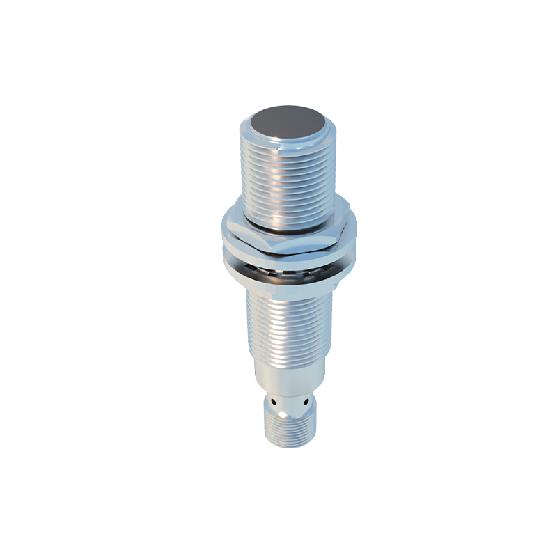
1. Power Supply Connection: Connect the positive terminal of the DC power supply to the brown wire of the first sensor. Connect the blue wire of the last sensor in the series to the negative terminal of the power supply.
2. Inter-sensor Wiring: Link the black output wire of the first sensor to the brown (positive) wire of the next sensor. Repeat this pattern for additional sensors.
3. Load Connection: The final output is taken from the black wire of the last sensor and connected to the load (e.g., a PLC input, relay, or indicator).
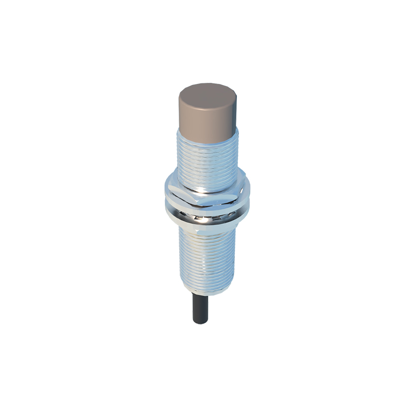
A diagram would illustrate this as a chain: Power (+) → Sensor 1 (Brown) → Sensor 1 (Black) → Sensor 2 (Brown) → Sensor 2 (Black) → ... → Last Sensor (Black) → Load → Power (-).
Key advantages of series wiring include reduced wiring complexity and cost, as fewer input points are needed on controllers. It also ensures synchronized operation, where all sensors must trigger simultaneously for an output. However, engineers must account for voltage drop across each sensor. In series circuits, the total voltage drop is the sum of individual drops. If too many sensors are connected, the voltage at the load may fall below the required threshold, causing malfunction. Always verify the cumulative voltage drop against the load’s specifications.
Another critical consideration is sensor compatibility. Most modern solid-state proximity sensors are designed for series wiring, but checking manufacturer datasheets is essential. Parameters like leakage current, residual voltage, and minimum operating voltage must be evaluated. For example, if each sensor has a residual voltage of 1V, connecting five in series could result in a 5V drop, potentially insufficient for a 24V system’s PLC input.
In practice, series wiring is common in safety circuits, conveyor belt sequencing, and multi-point inspection stations. For safety applications, using normally open (NO) sensors in series ensures that if any guard is opened, the circuit breaks, halting the machine. Conversely, for process control, series wiring can verify that all parts are correctly positioned before a robotic arm activates.
Troubleshooting series-wired sensors requires a systematic approach. Use a multimeter to measure voltage at each junction. If the load fails to activate, check for continuity through each sensor while actuating them individually. Remember that a single faulty sensor can break the entire circuit—a drawback of series configurations. Redundancy or parallel wiring may be preferable for critical non-safety functions where one sensor’s failure shouldn’t stop the process.
In summary, series wiring of proximity sensors is a valuable technique for creating logical AND conditions and simplifying control logic. By understanding the wiring diagram, voltage constraints, and application needs, engineers can implement robust and efficient sensor networks. Always prioritize safety standards like IEC 60947-5-2 and consult technical manuals to ensure reliable operation in harsh industrial environments.