In industrial automation and control systems, proximity switches are indispensable components for detecting the presence or absence of objects without physical contact. A critical yet often overlooked aspect of their installation and performance is the selection of the appropriate wire gauge for sensor connections. The correct wire size ensures reliable signal transmission, minimizes voltage drop, and enhances the overall safety and longevity of the system. This guide delves into the factors influencing wire gauge choice for proximity sensor applications, providing practical insights for engineers and technicians.
The wire gauge, typically expressed in American Wire Gauge (AWG) standards, directly affects electrical resistance and current-carrying capacity. For most standard 2-wire or 3-wire DC proximity sensors operating at 10-30V DC, common wire sizes range from AWG 18 to AWG 22. These sensors generally draw low currents, often between 100mA to 200mA, making finer gauges like AWG 22 suitable for short-run installations within control panels or machinery. However, when extending sensor cables over longer distances—exceeding 50 feet (15 meters)—voltage drop becomes a significant concern. Using a thicker wire, such as AWG 18 or even AWG 16, can mitigate this issue by reducing resistance, ensuring the sensor receives adequate voltage for stable operation.
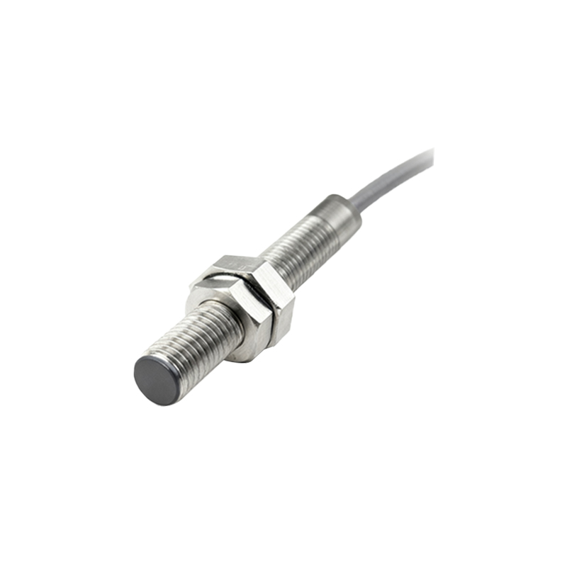
For AC-powered proximity switches or those with higher current demands, such as some 4-wire models with relay outputs, heavier gauges like AWG 16 or AWG 14 may be necessary. It is crucial to consult the sensor’s datasheet for specific current ratings and follow the National Electrical Code (NEC) or local regulations for current-carrying capacity. Environmental conditions also play a pivotal role. In high-temperature areas, wires may need to be derated, requiring a larger gauge to handle the same current safely. Similarly, for applications involving continuous flexing or vibration, such as on robotic arms, using stranded wires with a robust gauge (e.g., AWG 18) and proper shielding is advisable to prevent fatigue and electromagnetic interference.
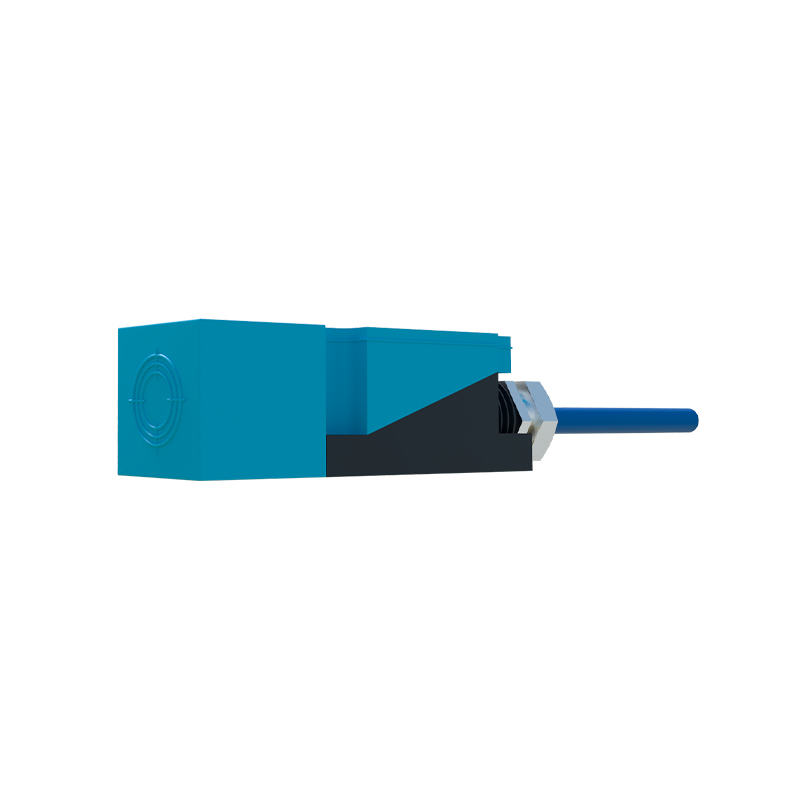
Shielding and insulation are equally important. Proximity sensors in electrically noisy environments, like those near motors or frequency drives, should use shielded cables (e.g., with a braided or foil shield) to prevent false triggering. The wire gauge should complement the shielding type; for instance, a thicker AWG 16 shielded cable might be used in complex factory setups. Additionally, insulation materials like PVC, PUR, or TPE should be selected based on exposure to oils, chemicals, or moisture, with gauge choices ensuring the insulation does not compromise flexibility or durability.
In practice, engineers must balance technical requirements with cost and practicality. While thicker wires offer better performance, they are more expensive and harder to route in tight spaces. A common recommendation is to perform a voltage drop calculation: Voltage Drop = (2 × Length × Current × Resistance per 1000ft) / 1000. For a 100-foot run with a 150mA sensor using AWG 22 wire (resistance ~16.5 ohms per 1000ft), the drop would be approximately 0.5V, which is acceptable for a 24V system. However, for longer runs, upgrading to AWG 18 (resistance ~6.5 ohms per 1000ft) reduces drop significantly. Always factor in a safety margin, especially for critical applications.
Ultimately, selecting the right wire gauge for proximity sensors involves analyzing current draw, distance, environmental factors, and regulatory standards. By adhering to these guidelines, professionals can optimize system reliability, reduce downtime, and ensure safe operation in diverse industrial settings.