Inductive proximity sensors are fundamental components in industrial automation, widely used for non-contact detection of metallic objects. This experiment guide provides a detailed, hands-on approach to understanding their operation, characteristics, and practical applications. The core principle relies on electromagnetic induction. The sensor generates an oscillating electromagnetic field via a coil wound around a ferrite core. When a metallic target enters this field, eddy currents are induced on the target's surface. These currents absorb energy from the oscillator, causing a change in its amplitude. This change is detected by the sensor's trigger circuit, which subsequently switches the output state.
To conduct a basic experiment, you will need the following equipment: a 12-24V DC inductive proximity sensor (typically a cylindrical M12 or M18 form factor), a compatible DC power supply, a set of metallic test targets (e.g., mild steel, aluminum, brass, and copper plates of varying thicknesses), a non-metallic target for comparison, a digital multimeter, an oscilloscope (optional for waveform analysis), and connecting wires. Always adhere to standard electrical safety protocols, ensuring the power is off during initial wiring.
Begin by connecting the sensor according to its wiring scheme (PNP normally open or NPN normally closed). Apply the rated voltage. The first experiment involves determining the sensor's rated operating distance (Sn). This is the nominal sensing distance for a standard 1mm thick, square mild steel target. Gradually bring the steel target towards the sensor's active face along the axial centerline. Use a non-metallic ruler for precision. Record the exact distance at which the output LED indicator switches and the output signal changes state. Repeat this process several times to ensure consistency. This measured value should be close to the manufacturer's specification. Note that the actual sensing distance can be affected by factors like target material, size, and temperature.
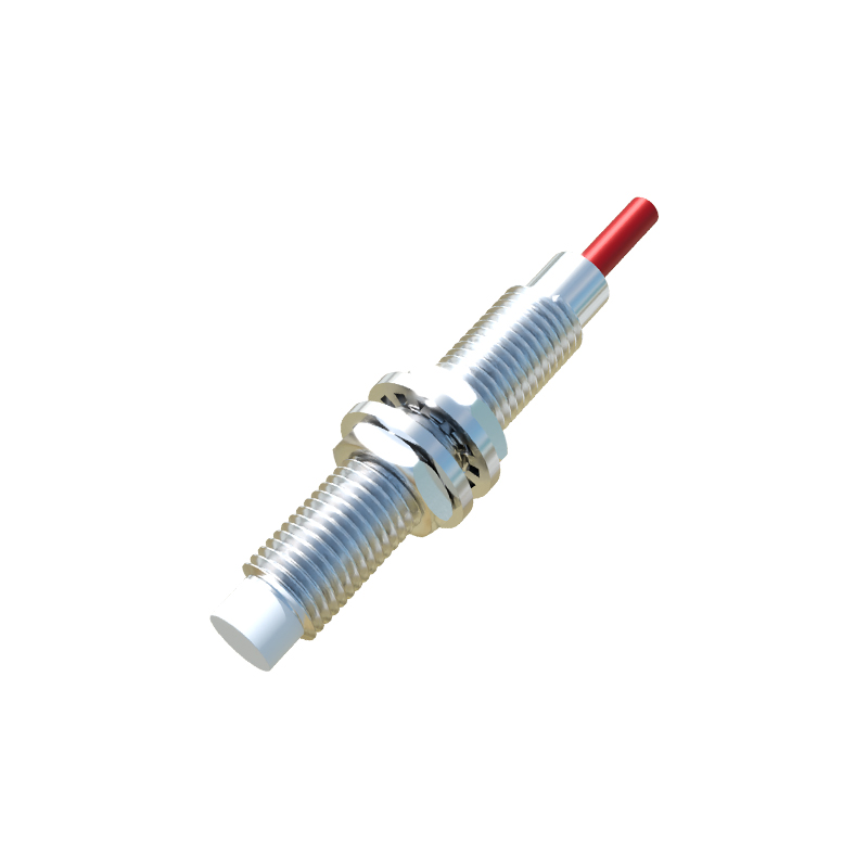
The second key experiment investigates the influence of target material. Different metals have different electrical conductivities and magnetic permeabilities, which affect eddy current generation. Test the same sensor with targets of identical size and shape made from mild steel, stainless steel, aluminum, brass, and copper. You will observe a significant variation in the effective switching distance. For instance, mild steel (ferromagnetic) typically achieves 100% of Sn, while aluminum (non-ferrous, good conductor) might achieve only 40-50% of Sn. Copper may yield an even lower factor. This experiment highlights the critical importance of material correction factors specified in datasheets for real-world application design.
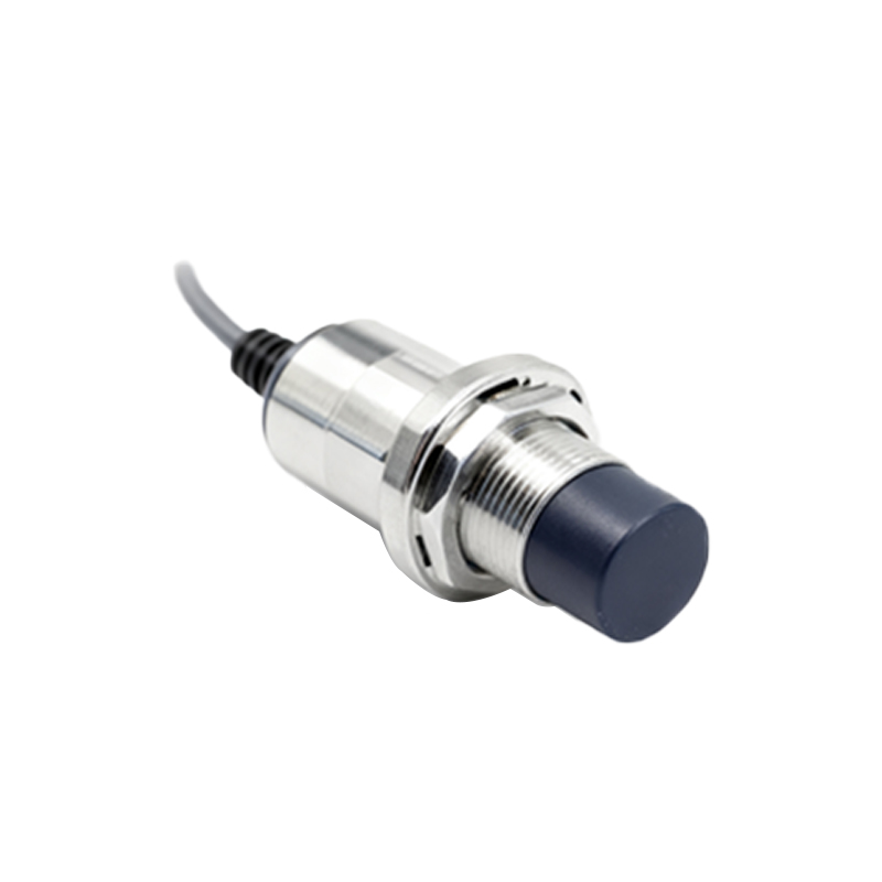
Next, explore the concept of hysteresis. This is the difference between the switch-on point (as the target approaches) and the switch-off point (as the target recedes). Hysteresis is a built-in feature to prevent output chatter when a target is positioned exactly at the sensing edge. To measure it, slowly move the target towards the sensor until it activates. Mark this distance (Switch-On Point). Then, slowly move the target away until the output deactivates. Mark this new distance (Switch-Off Point). The difference between these two distances is the hysteresis. It is usually expressed as a percentage of the operating distance (e.g., 3-10% of Sn). This parameter ensures stable switching even in the presence of mechanical vibration.
For a more advanced analysis, use an oscilloscope to monitor the oscillator's signal at the sensing coil (if accessible) or the output transistor's switching behavior. Observe the change in the oscillation envelope as a metal target enters the field. You can also measure the sensor's repeat accuracy by repeatedly positioning the target at the switch point and measuring the variance in the switching distance. Furthermore, test the effects of lateral misalignment and the presence of an adjacent metal object (shielding effect), which are common installation challenges.
In conclusion, this systematic experimentation demystifies the operational parameters of inductive proximity sensors. Understanding the rated operating distance, material dependence, hysteresis, and environmental factors is paramount for selecting the correct sensor for a specific task, such as position verification in a conveyor system, counting metal parts, or end-of-travel detection in machinery. Always consult the manufacturer's datasheet for precise specifications, as performance can vary between models and brands. This hands-on knowledge forms the bedrock of reliable and efficient industrial control system design.