Proximity sensors are essential components in modern industrial automation, providing non-contact detection of metallic or non-metallic objects. Proper wiring is critical to ensure reliable operation, safety, and longevity of these sensors. This article explores common wiring types and methods for proximity sensors, focusing on practical considerations for engineers and technicians.
There are two primary wiring configurations for proximity sensors: 2-wire and 3-wire systems. Each type has distinct characteristics and applications.
2-Wire Proximity Sensors
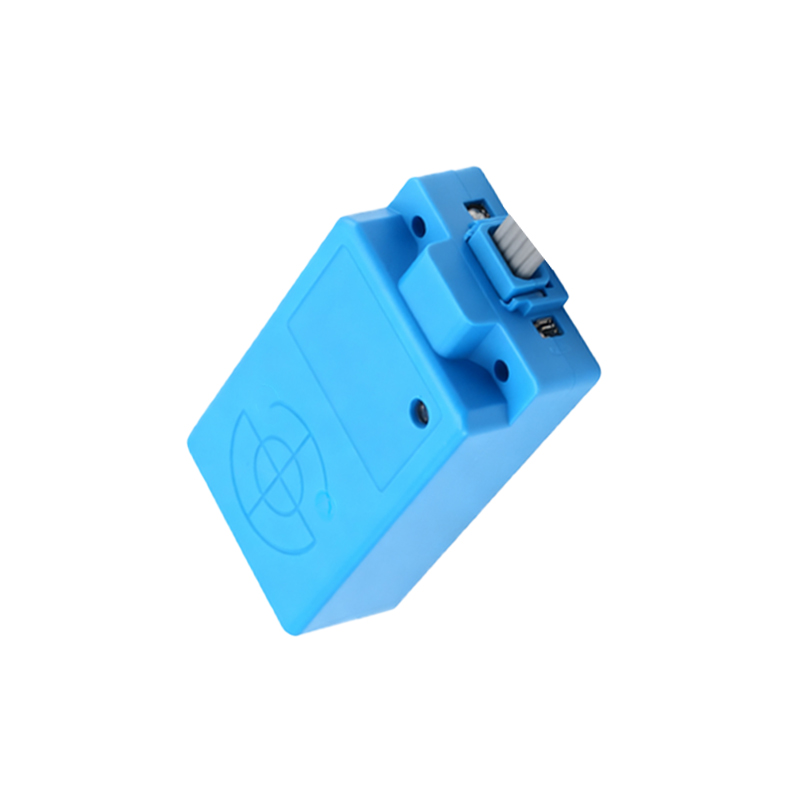
2-wire sensors are simpler in design and directly connected in series with the load. They function similarly to a switch, making them easy to integrate into existing circuits. However, they have a residual current (leakage current) when in the "off" state, which can sometimes cause issues with sensitive loads. Key considerations include:
- Ensure the load impedance is within specified limits to avoid malfunction.
- Voltage drop across the sensor must be accounted for in low-voltage applications.
- Polarity is typically not a concern, as most 2-wire sensors are AC-operated or polarity-insensitive.
3-Wire Proximity Sensors
3-wire sensors are more common in DC applications and offer better performance with minimal leakage current. They consist of power supply wires (typically brown for positive, blue for negative) and a separate output wire (black, white, or gray). There are two output types:
1. NPN (Sinking Output): The output switches the negative side of the load to ground. Common in European and Asian markets.
2. PNP (Sourcing Output): The output provides positive voltage to the load. Widely used in North America.
Wiring must match the sensor's output type and the control system's input requirements. Incorrect wiring can lead to sensor damage or system failure.
Wiring Methods and Best Practices
1. Shielded Cables: Use shielded cables in environments with high electromagnetic interference (EMI) to prevent false triggering. Ground the shield at one end only, typically at the control panel.
2. Cable Gland and Strain Relief: Proper mechanical protection prevents cable damage from vibration, tension, or environmental factors.
3. Power Supply Considerations: Ensure stable voltage within the sensor's rated range. Ripple and noise can affect performance. For DC sensors, a regulated power supply is recommended.
4. Parallel and Series Connections: Avoid connecting multiple sensors in parallel or series unless specified by the manufacturer, as this can affect current draw and switching characteristics.
5. Load Compatibility: Verify that the sensor's output current and voltage ratings are compatible with the connected load (e.g., PLC input, relay coil). Overloading can shorten sensor life.
Installation Tips
- Maintain adequate clearance between sensors and metal surfaces to prevent interference.
- Follow manufacturer guidelines for sensing distance and alignment.
- Use conduit or cable trays in harsh industrial environments to protect wiring from chemicals, moisture, or physical damage.
Troubleshooting Common Issues
- No Output: Check power supply, wiring connections, and load compatibility.
- Intermittent Operation: Inspect for loose connections, EMI, or environmental factors like dust accumulation.
- Sensor Damage: Ensure voltage spikes are suppressed with protective devices like surge suppressors.
In summary, selecting the correct wiring type and method for proximity sensors depends on the application requirements, control system design, and environmental conditions. Adhering to standards such as IEC 60947-5-2 and manufacturer specifications ensures optimal performance and safety. Regular maintenance and proper installation are key to maximizing sensor reliability in industrial automation systems.