Laser sensors are widely used in industrial automation, robotics, and safety systems due to their high precision and reliability. Proper wiring is crucial for ensuring optimal performance and preventing damage to the sensor or connected equipment. This guide provides a detailed overview of laser sensor wiring methods, covering common types, connection steps, and best practices for electrical engineers.
First, it is essential to understand the basic components of a laser sensor. Typically, a laser sensor consists of a transmitter (laser emitter), a receiver (photodetector), and an output circuit. The sensor may operate on different principles, such as through-beam, retro-reflective, or diffuse reflection, each requiring specific wiring considerations. Most industrial laser sensors use DC power supplies, commonly 12-24V DC, and provide digital or analog outputs (e.g., NPN, PNP, 4-20mA, 0-10V).
Before starting the wiring process, always refer to the sensor's datasheet for voltage ratings, pin configurations, and safety instructions. Disconnect all power sources to avoid electrical hazards. The general wiring steps are as follows:
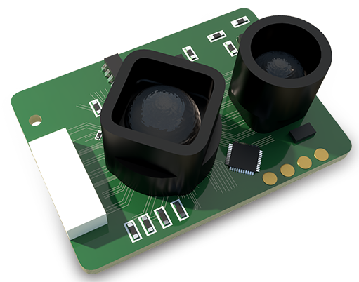
1. Power Supply Connection: Connect the positive terminal of the DC power supply to the sensor's V+ or brown wire (according to IEC standards), and the negative terminal to the sensor's V- or blue wire. Ensure the voltage matches the sensor's specifications—overvoltage can cause permanent damage.
2. Output Connection: Laser sensors often have switching outputs to control external devices like PLCs, relays, or indicators. For NPN (sinking) outputs, connect the load between the output wire (usually black) and the positive supply; for PNP (sourcing) outputs, connect the load between the output wire and ground. Analog outputs require direct connections to measurement devices, with shielding to reduce noise interference.
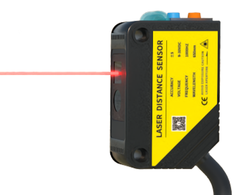
3. Grounding and Shielding: Proper grounding minimizes electrical noise and enhances stability. Use a dedicated ground wire (green-yellow) connected to an earth ground point. For sensors in high-interference environments, employ shielded cables and connect the shield to ground at one end only to prevent ground loops.
4. Safety Circuits: In safety-critical applications (e.g., laser guards), integrate the sensor with safety relays or controllers. Wire the sensor's safety output to a monitored circuit that can trigger machine shutdown if the laser beam is interrupted.

5. Testing and Calibration: After wiring, power on the sensor and verify its operation using a multimeter or oscilloscope. Adjust sensitivity and response time as needed, and ensure the laser beam is aligned correctly for accurate detection.
Common pitfalls include incorrect polarity, loose connections, and inadequate wire gauges. Use stranded copper wires with appropriate current ratings, and secure connections with crimp terminals or soldering. For long-distance wiring (over 50 meters), consider voltage drop and use thicker wires or signal amplifiers.
In summary, wiring a laser sensor requires attention to electrical standards, environmental factors, and application needs. By following these guidelines, engineers can ensure reliable sensor performance, reduce downtime, and enhance system safety. Regular maintenance, such as checking connections and cleaning lenses, further prolongs sensor life.