In the realm of industrial automation and control systems, proximity switch sensors are indispensable components for non-contact detection of objects. Their reliable operation, however, is fundamentally dependent on one critical yet often underappreciated element: the power cable connector. This component serves as the vital lifeline, transmitting both power and, in many cases, signal data between the sensor and the control system. A poor connection can lead to sensor malfunction, intermittent operation, or complete system failure, resulting in costly downtime. This guide delves into the intricacies of proximity switch sensor power cable connectors, offering insights for electrical engineers to ensure optimal selection, installation, and maintenance.
The primary function of these connectors is to provide a secure, stable, and protected electrical interface. Proximity sensors typically operate on low-voltage DC power, commonly 10-30V DC, though AC variants exist. The connector must therefore be rated for the appropriate voltage and current, with a sufficient safety margin. Beyond basic electrical specifications, the industrial environment imposes severe demands. Connectors are subjected to vibration, mechanical stress, temperature extremes, moisture, oils, coolants, and chemical exposure. Consequently, the choice of connector is dictated by its Ingress Protection (IP) rating. For harsh environments like washdown areas in food processing or outdoor applications, connectors with high IP ratings (e.g., IP67, IP68, IP69K) are mandatory to prevent ingress of dust and water.
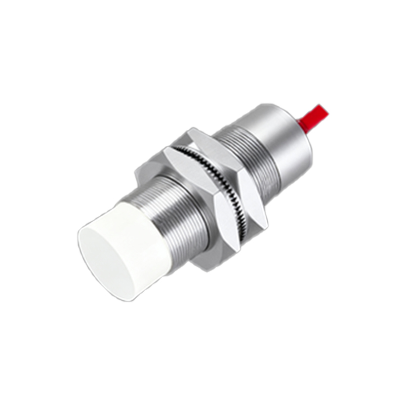
Connector types for proximity sensors are largely standardized, though variations exist by manufacturer and region. The most prevalent styles include the M8 and M12 circular connectors. The M8 connector, with its 8mm thread, is compact and ideal for space-constrained applications and smaller sensors. The M12 connector, with a 12mm thread, is the industry workhorse, offering robustness and a wide range of pin configurations (3-pin, 4-pin, 5-pin). A 3-pin M12 is standard for DC sensors (power +, power -, and signal output), while 4-pin versions often accommodate sensors with dual outputs or separate output and diagnostic lines. The coding system (A-coded, B-coded, etc.) is crucial; it prevents mismating sensors with incompatible devices. A-coded M12 connectors are almost universally used for standard sensors, fieldbus, and Ethernet, while B-coded are for fieldbus networks like Profibus. Engineers must verify the sensor's datasheet for the required coding.
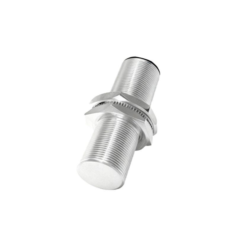
Beyond circular types, rectangular connectors or proprietary quick-disconnect styles are used for specific sensor families. The trend towards IO-Link, a point-to-point serial communication protocol, has also influenced connector standards. Many modern sensors with IO-Link capability still use the standard M12 connector but utilize the additional pins for digital communication, enabling advanced diagnostics, parameter setting, and process data exchange without changing the physical interface.
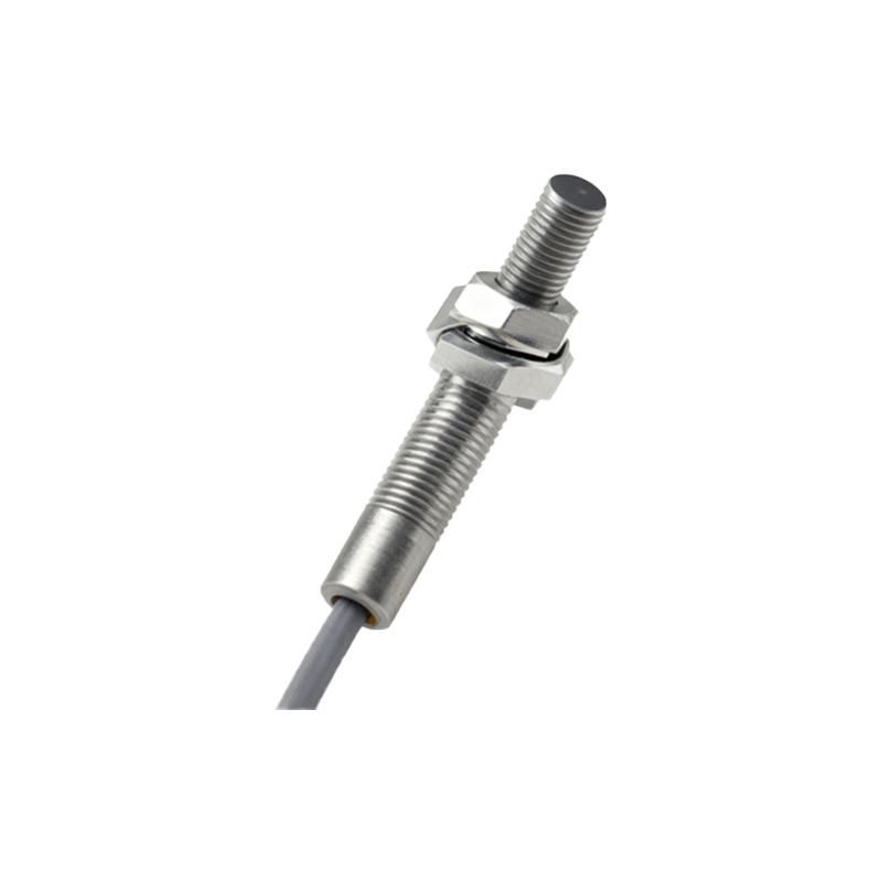
Installation practices are paramount. Proper cable preparation is the first step. Stripping the cable jacket to the correct length, trimming individual conductors, and crimping the pins or sockets with a calibrated tool are non-negotiable steps for a reliable connection. A poor crimp is a primary source of failure. The connector should be assembled according to the manufacturer's instructions, ensuring all seals (o-rings, grommets) are correctly seated. The mating between the plug (on the cable) and the receptacle (on the sensor) must be done carefully, aligning the pins and engaging the thread smoothly. Over-tightening can damage the threads or crack the housing, while under-tightening compromises the seal. A final tug test on the cable ensures it is securely locked in the connector strain relief.
Maintenance involves regular visual inspections for physical damage, corrosion, or cracked housings. In environments with high vibration, checking the tightness of the connector locknut is advisable. Never disconnect a connector under load if the sensor specifications prohibit it. When troubleshooting sensor issues, the connector is a logical first checkpoint. A multimeter can check for continuity in the cable and correct voltage at the sensor pins. Look for signs of fretting corrosion on the pins—a common issue in vibratory environments that increases resistance and causes signal dropouts.
In conclusion, the power cable connector is far more than a simple piece of plastic and metal. It is an engineered interface critical to system integrity. For electrical engineers, specifying a connector with the correct electrical rating, mechanical form factor, IP protection, and coding is essential. Coupling this with disciplined installation and proactive maintenance forms the bedrock of a reliable, high-uptime automation system. By giving these components the attention they deserve, engineers can prevent a multitude of field failures and ensure that proximity sensors perform their detection duties flawlessly, day in and day out.