Proximity sensors are indispensable components in modern industrial automation, machinery, and control systems. As non-contact devices, they detect the presence or absence of an object within their sensing range, playing a critical role in positioning, counting, and safety applications. When a proximity sensor fails, it can lead to unexpected machine downtime, production losses, and potential safety hazards. This guide provides a systematic, industry-standard approach for electrical engineers and technicians to diagnose and repair common proximity sensor faults.
Initial Safety and Verification Procedures
Before any troubleshooting begins, adhere to strict lockout/tagout (LOTO) procedures to isolate the equipment from all energy sources. Verify the system is de-energized and safe to work on. The first step is to confirm the failure. Symptoms of a faulty proximity sensor may include: intermittent operation, complete failure to detect objects, constant "on" state regardless of object presence, or erratic output signals. Check the machine's Human-Machine Interface (HMI) or Programmable Logic Controller (PLC) for any active fault codes related to the sensor's input module.
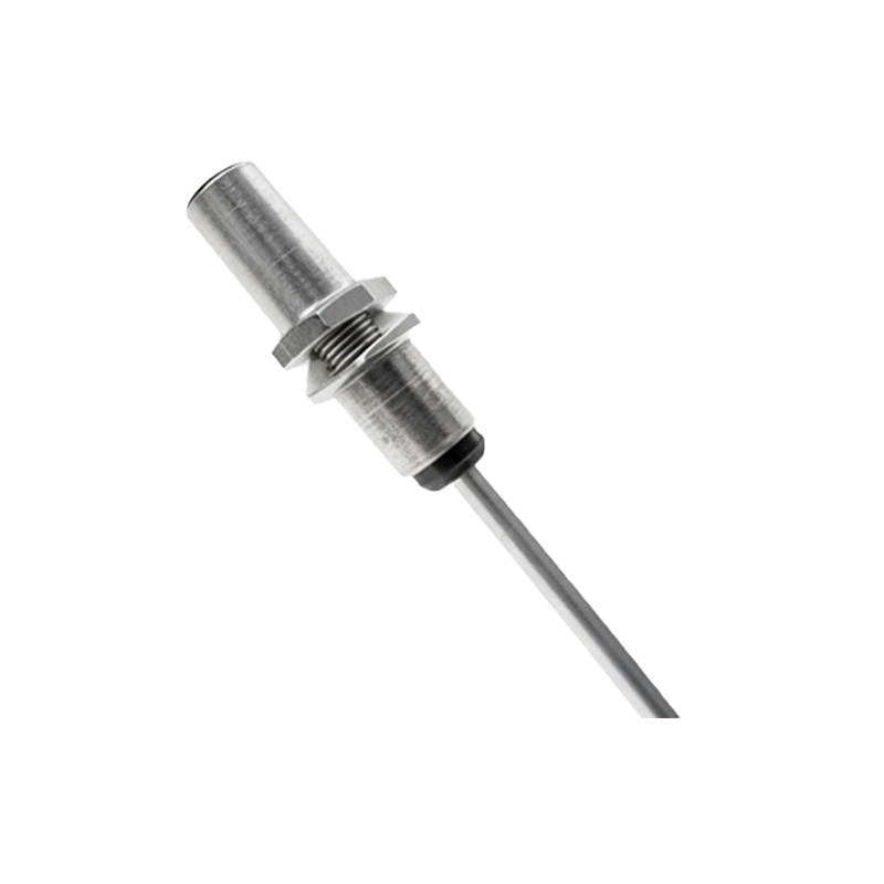
Step 1: Visual Inspection and Physical Check
Conduct a thorough visual inspection of the sensor, its mounting, and the surrounding area.
Physical Damage: Look for cracks in the sensor housing, dents, or signs of impact. Damage to the sensing face is a common cause of failure.
Mounting and Alignment: Ensure the sensor is securely mounted. Loose mounting can cause vibration-induced failure or misalignment with the target object. Verify the gap between the sensor and the target is within the specified sensing range. Metallic debris or buildup on the sensing face can also interfere with operation.
Connections and Wiring: Inspect the sensor's cable and connector for cuts, abrasions, pinch points, or corrosion. A damaged cable is one of the most frequent failure points. Check that the connector is fully seated and locked.
Step 2: Electrical Diagnostics with a Multimeter
If the visual inspection reveals no obvious issues, proceed with electrical testing. You will need a digital multimeter capable of measuring DC voltage and continuity/resistance.
Power Supply Verification: Re-apply power to the circuit (safely, following LOTO restoration procedures). Measure the voltage between the sensor's supply (typically brown wire for +V, blue for 0V/Common) terminals. Ensure it matches the sensor's rated voltage (e.g., 10-30V DC). A low or absent voltage indicates a problem with the power supply or upstream wiring, not necessarily the sensor itself.
Output Signal Testing: For a DC 3-wire sensor (PNP or NPN), measure the voltage between the output wire (typically black) and the common (blue). With no target present, the output should be near 0V (for a normally open sensor). When a valid target is brought within the sensing range, the output should switch to either the supply voltage (for PNP) or remain near 0V (for NPN sinking). An incorrect or fluctuating reading indicates an internal sensor fault.
Continuity and Short Circuit Test (Power Off): Disconnect the sensor. Check for short circuits between the power, output, and common wires. Also, check for continuity between the sensor body (metal parts) and the wires to rule out a ground fault. High resistance or unexpected shorts suggest internal component failure.
Step 3: Environmental and Load Considerations
Sensor performance can be degraded by environmental factors.
Electrical Noise: Install the sensor cable away from high-voltage power lines, motor drives, and welding equipment. Consider using shielded cables grounded at one end if noise susceptibility is suspected.
Load Current: Verify the sensor's output is not connected to a load (e.g., a relay coil, PLC input) that exceeds its maximum rated current. An overload can damage the sensor's output transistor.
Temperature and Contaminants: Ensure the ambient temperature is within the sensor's specification. Exposure to oils, coolants, or chemicals not rated for the sensor's housing (e.g., IP67) can lead to ingress and internal corrosion.
Step 4: Substitution and Final Verification
The most definitive test is substitution with a known-good sensor of the same type and model. Ensure the replacement has identical specifications: sensing type (inductive, capacitive), sensing range, output configuration (PNP/NPN, NO/NC), voltage rating, and physical size. After replacement, perform a full functional test. Cycle the machine and verify the sensor triggers consistently under normal operating conditions. Monitor the PLC input status to confirm clean, reliable signal transitions.
Repair vs. Replacement Decision
Most modern proximity sensors are sealed, pot